Bearing device for wheel

A technology for bearing devices and wheels, which is applied to bearings, bearing components, roller bearings, etc., and can solve problems such as not being able to obtain optimal stiffness

Active Publication Date: 2009-08-19
NTN CORP
View PDF1 Cites 13 Cited by
  • Summary
  • Abstract
  • Description
  • Claims
  • Application Information

AI Technical Summary

Problems solved by technology

[0004] In the prior art wheel bearing device formed of double-row rolling bearings, since the bearing structures in the left and right rows are the same, although it has sufficient rigidity during straight running, it cannot always obtain the optimum stiffness during curve running. Best stiffness

Method used


Image

  • Bearing device for wheel
  • Bearing device for wheel
  • Bearing device for wheel

Examples


no. 1 approach

[0117] Preferred embodiments of the present invention will be described below with reference to the accompanying drawings.

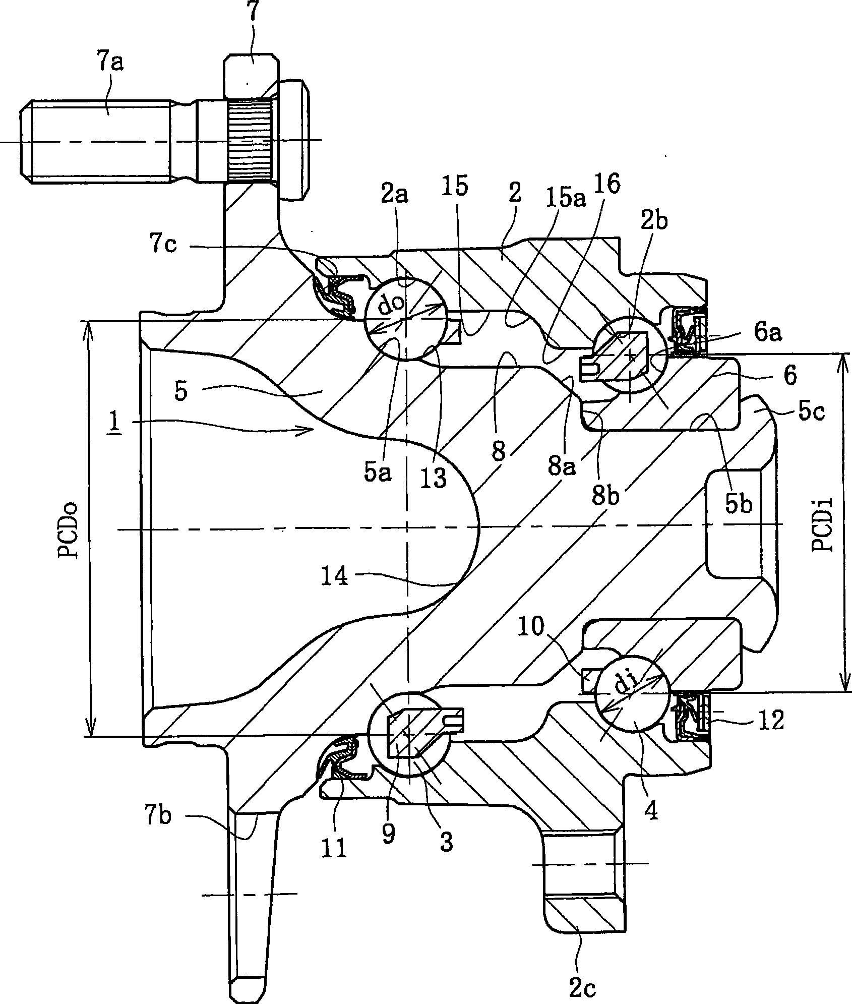
[0118] figure 1 It is a longitudinal sectional view showing the first embodiment of the wheel bearing device of the present invention.

[0119] figure 1 The wheel bearing device of the present invention shown is of the third generation type for driven wheels and comprises an inner part 1, an outer part 2 and a double row ball set rotatably accommodated between the inner part 1 and the outer part 2 3, 4. The inner part 1 includes a wheel hub 5 and an inner ring 6 press-fitted on the wheel hub 5 with a predetermined interference.

[0120] The wheel hub 5 is integrally formed with a wheel mounting flange 7 at one end thereof, an (outer) inner raceway surface 5a having a circular arc-shaped cross-section on its outer periphery, and a shaft-like portion 8 extending from the inner raceway surface 5a. The cylindrical part 5b. A plurality of hub bolts 7a ...

no. 2 approach

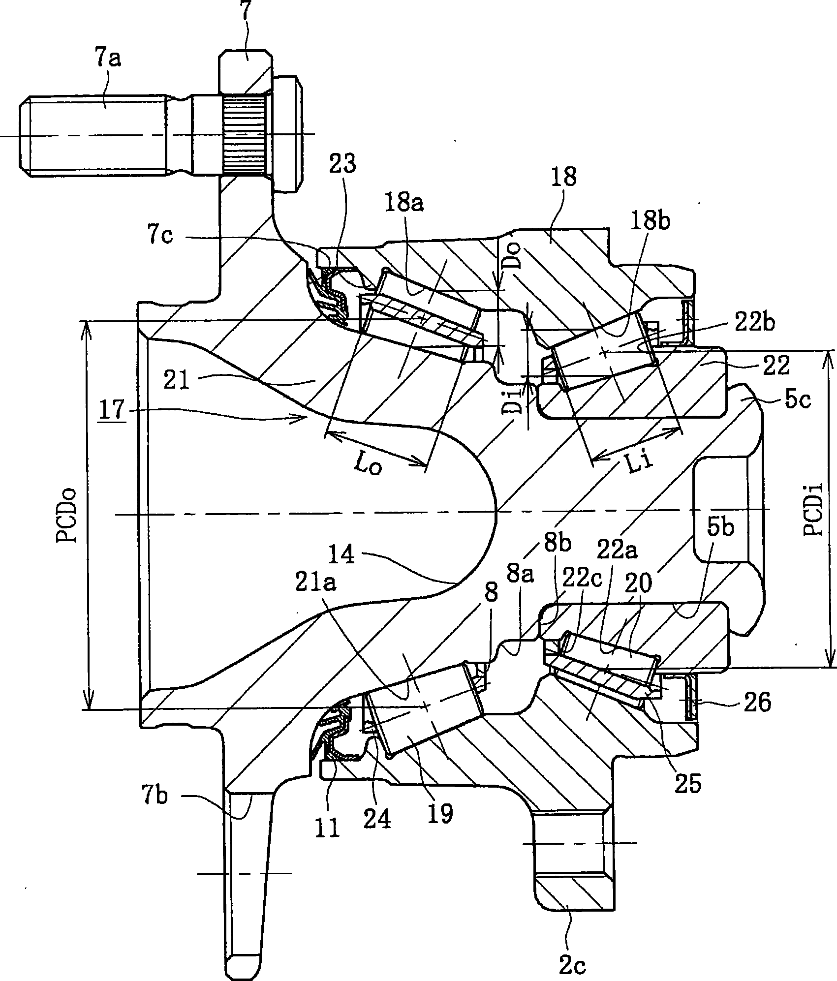
[0130] figure 2 It is a longitudinal sectional view showing a second embodiment of the wheel bearing device of the present invention. The same reference numerals are used here to denote the same components having the same functions as those used in the first embodiment.

[0131] figure 2The wheel bearing device of the present invention shown is of the third generation type for driven wheels and comprises an inner part 17, an outer part 18 and a double row cone which is accommodated freely rolling between the inner part 17 and the outer part 18. Shape roller 19,20. The inner member 17 includes a wheel hub 21 and an inner ring 22 press-fitted on the wheel hub 21 with a predetermined interference.

[0132] The wheel hub 21 is integrally formed with a wheel mounting flange 7 at one end thereof, a (outer) tapered inner raceway surface 21a on its outer periphery, and a shaft extending from the inner raceway surface 21a through an axially extending shaft-like portion 8. Cylindr...

no. 3 approach

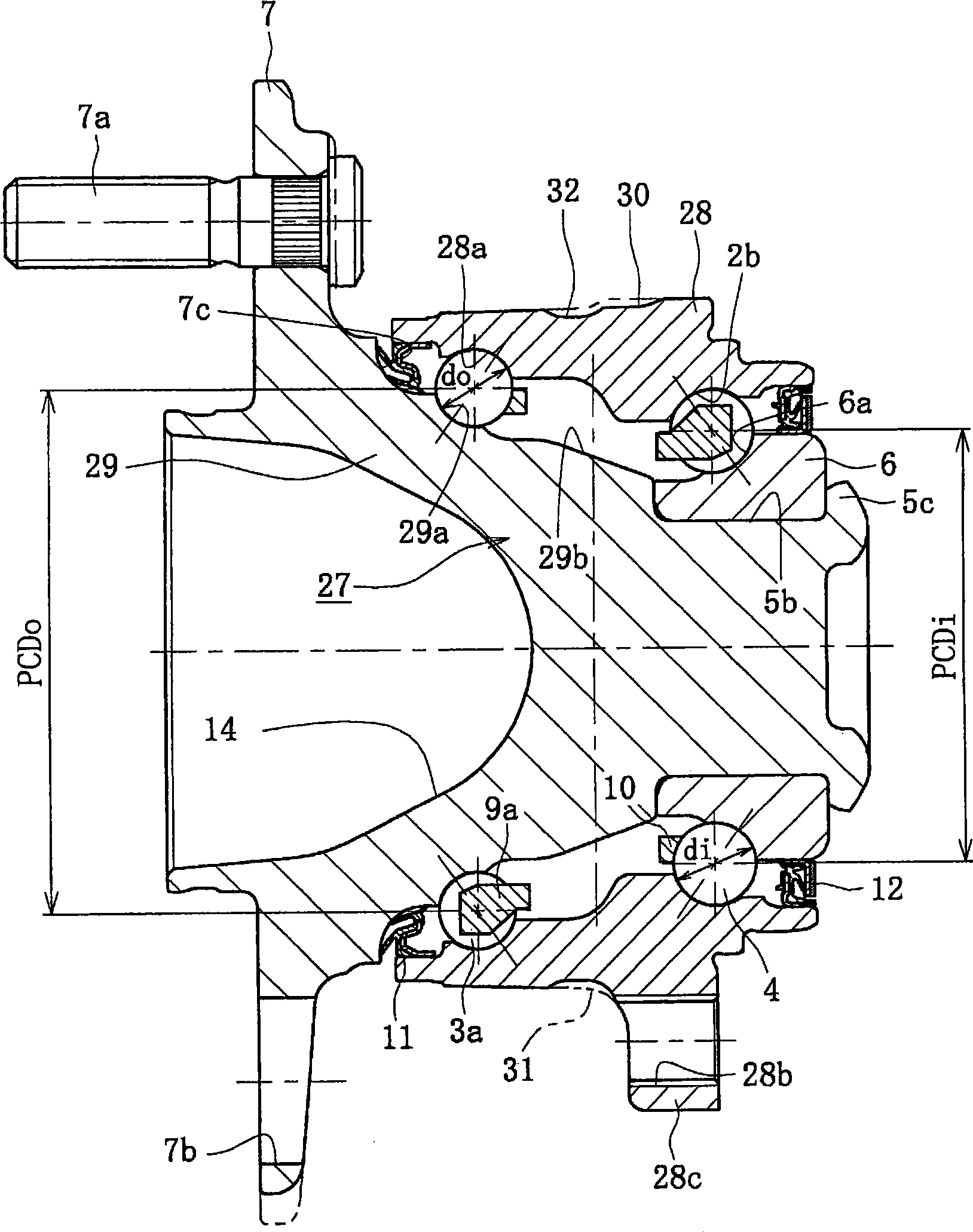
[0140] image 3 is a longitudinal sectional view showing a third embodiment of the wheel bearing device of the present invention, Figure 4 yes image 3 side view, Figure 5 yes image 3 A partial enlargement of the . The same reference numerals are used here to denote the same components having the same functions as those used in the previous embodiments.

[0141] image 3 The wheel bearing device of the present invention shown is of the third generation type for driven wheels and comprises an inner part 27, an outer part 28 and a double row of balls housed freely rolling between the inner part 27 and the outer part 28 Group 3a, 4. The inner member 27 includes a wheel hub 29 and the inner ring 6 press-fitted on the wheel hub 29 with a predetermined interference.

[0142] The wheel hub 29 is integrally formed with the wheel mounting flange 7 at its outer end, an (outer) inner race surface 29a on the outer periphery, and a cylindrical portion extending from the inner rac...


PUM


Abstract

To provide a wheel bearing device which is made light and compact while increasing the rigidity of a bearing. In the wheel bearing device, a pitch circle diameter PCDo of a ball group 3 located close to a wheel mounting flange 7, out of double row ball groups 3, 4, is set to be larger than a pitch circle diameter PCDi of the ball group 4 located far from the wheel mounting flange 7. A ball diameter do of the ball group 3 located close to the wheel mounting flange 7 is set to be larger than a ball diameter di of the ball group 4 located far from the wheel mounting flange 7, the ball number of the former is set to be more than that of the latter. A mortary recessed portion 14 is formed in the end on the outer side of a hub ring 5. The depth of the mortary recessed portion 14 reaches the vicinity of at least shaft portion 8, and the shell of the hub ring 5 is shaped with its thickness approximately uniform. This solves conflicting problems on the device which is lighter/compacter as well as highly rigid.

Description

technical field [0001] The present invention relates to a bearing device for a wheel, and more particularly, to a bearing device for a wheel for a vehicle that can increase bearing rigidity and reduce the weight and size of the bearing device for a wheel. Background technique [0002] Generally, the bearing device for a wheel is adapted to freely rotatably support a hub wheel for mounting a wheel through a rolling bearing, and adopts an inner ring rotation type for a driving wheel and an inner ring rotation type and an outer ring rotation type for a driven wheel. Double row angular contact ball bearings are widely used in such bearing devices because of their desired bearing rigidity, high misalignment resistance, and small torque required for low fuel consumption. A double row angular contact ball bearing has a plurality of balls interposed between a stationary ring and a rotating ring, and the balls are in contact with the stationary ring and the rotating ring at a predete...

Claims


Application Information

Patent Timeline
Patent Type & Authority Applications(China)
IPC IPC(8): F16C33/32F16C19/18F16C19/38F16C33/36
CPCY02T10/86
Inventor 小森和雄马场智子木内政浩
Owner NTN CORP
Why Eureka
Try Eureka