Refrigerator

A technology of refrigeration equipment and refrigerants, which is applied in the direction of lighting and heating equipment, refrigerators, refrigeration components, etc., to achieve the effect of cheap manufacturing and molding

Inactive Publication Date: 2011-07-27
BOSCH SIEMENS HAUSGERATE GMBH
View PDF0 Cites 0 Cited by
  • Summary
  • Abstract
  • Description
  • Claims
  • Application Information

AI Technical Summary

Problems solved by technology

Again, however, when the blower has to be started during compressor operation, a perceivable and objectionable noise level is produced

Method used


Image

  • Refrigerator
  • Refrigerator
  • Refrigerator

Examples


Embodiment Construction

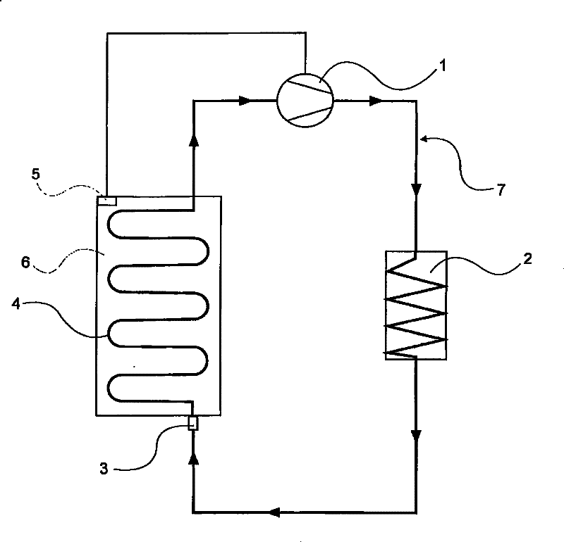
[0021] figure 1 Schematically illustrates the refrigeration cycle of a refrigeration plant. The refrigerating circuit comprises a compressor 1, a condenser 9, a throttling device 3 and an evaporator 4 with a thermostat 5, said compressor and condenser being located outside the cooling interior 6 of the refrigerating device, said throttling device being located in the cooling At the edge of the interior 6 , an evaporator with a thermostat is located inside the cooling interior 6 . The condenser generally consists of a piping system of serpentine coils which dissipate the heat of the gaseous refrigerant 7 to the outside air and in doing so condense the refrigerant. The refrigeration cycle occurs in a closed circuit filled with refrigerant. In the compressor 1, the gaseous refrigerant 7 is compressed and heated through a compression process. In the condenser 9, heat is removed from the gaseous refrigerant 7 and discharged to the outside air, in which process the refrigerant i...


PUM


Abstract

The invention is based on a refrigerator with a cooled inner chamber (6) and a cooling circuit for a refrigerant (2, 7), wherein the cooling circuit has a heat exchanger (4) in the cooled inner chamber (6), a compressor (1) for the refrigerant (7) and a condenser (9) on the outside of the refrigerator. According to the invention, a heat-storage material (10) is in contact with the condenser (9).

Description

technical field [0001] The invention relates to a refrigeration device. Background technique [0002] In order to cool the interior of a refrigeration appliance, a refrigeration circuit is usually provided, in which circuit a refrigerant circulates. Outside the refrigerator, the refrigeration circuit includes a condenser, via which the heat absorbed by the refrigerant inside the refrigerator is dissipated to the outside air. In order to be able to ensure the necessary heat exchange, the condenser must have certain dimensions, especially in the case of built-in appliances, at the expense of cooling the interior. [0003] Essentially, the condenser must be designed in such a way that the heat generated during the operation of the compressor can also be removed during the operation of the compressor. During compressor shutdown, substantially no heat is generated. Therefore, at these times, there is also no need to transfer heat from the condenser to the outside air. Theref...

Claims


Application Information

Patent Timeline
Patent Type & Authority Patents(China)
IPC IPC(8): F25D23/00F25B39/04
CPCF25B2339/047F25B2339/046F25D23/003F25B39/04
Inventor N·利恩加德
Owner BOSCH SIEMENS HAUSGERATE GMBH
Why Eureka
Try Eureka