Unlock instant, AI-driven research and patent intelligence for your innovation.

Projection type image display device

一种图像显示装置、投影的技术,应用在放映装置、静态指示器、光学等方向,能够解决冷却风扇转速上升、返回光增多、噪音增大等问题,达到抑制风扇转速的过高、确保可靠性、减低噪音的效果

Active Publication Date: 2009-08-26
PANASONIC CORP
View PDF1 Cites 1 Cited by
  • Summary
  • Abstract
  • Description
  • Claims
  • Application Information

AI Technical Summary

Problems solved by technology

[0010] However, there is the following technical problem: when the light quantity of the lamp is increased according to the above-mentioned requirements, or when the aperture is fully closed, the return light reflected from the aperture increases, causing light damage to peripheral components such as the lamp and the fixing fixture. heat damage
[0012] In addition, the conventional method measures the temperature near the lamp, so the temperature of the bulb (bulb) itself of the lamp which becomes high temperature cannot be accurately measured.
[0013] Therefore, there is a problem that in order to ensure the reliability of the lamp, it is necessary to consider the margin of the cooling capacity, and the rotation speed of the cooling fan is also increased, and the noise is also increased.

Method used


Image

  • Projection type image display device
  • Projection type image display device
  • Projection type image display device

Examples


Embodiment approach 1

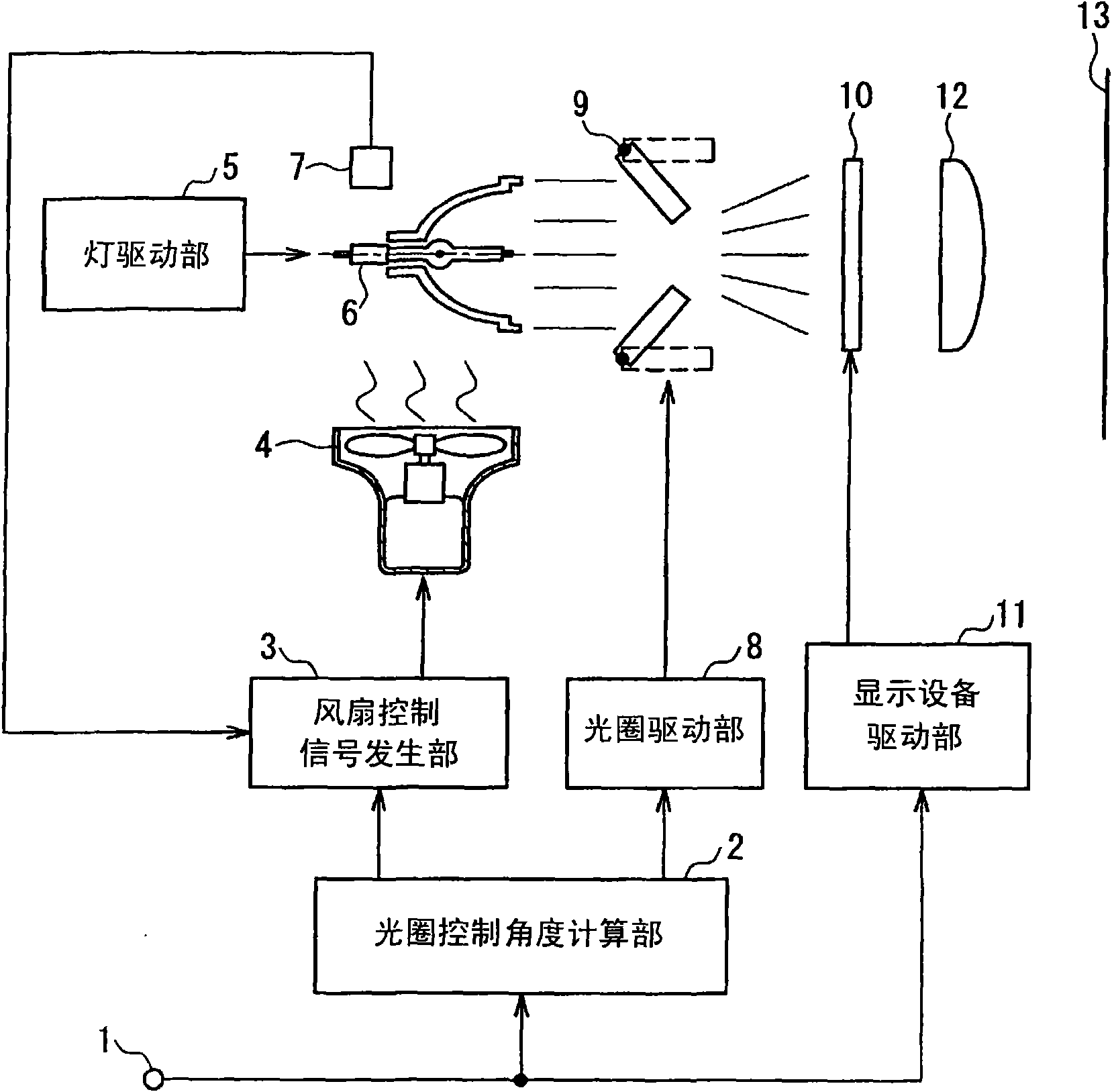
[0043] figure 1 It is a block diagram showing the configuration of the projection type image display device in Embodiment 1 of the present invention.

[0044] exist figure 1 Among them, the video signal input from the video signal input terminal 1 is supplied to the aperture control angle calculation unit 2 and the display device driving unit 11 . The aperture control angle calculation unit 2 has a function of calculating information on the control angle of the aperture according to the characteristics of the video signal. The control angle information output by the diaphragm control angle calculation unit 2 is supplied to the fan control signal generation unit 3 and the diaphragm driving unit 8 . The fan control signal generator 3 controls the rotation speed of the cooling fan 4 based on ambient temperature information and control angle information from the temperature sensor 7 .

[0045] The power of the lamp 6 is controlled by the lamp drive unit 5 , and the emitted ligh...

Embodiment approach 2

[0059] image 3 It is a block diagram showing the configuration of the projection type image display device in Embodiment 2 of the present invention. exist image 3 in, for and figure 1 Components that are the same as in the first embodiment shown are denoted by the same reference numerals, and description thereof will be omitted.

[0060] In Embodiment 1, the control angle information output from the aperture control angle calculation unit 2 is used as an input signal to the fan control signal generation unit 3 . On the other hand, in this embodiment, as the input signal to the fan control signal generator 3, a signal obtained by processing the video signal input from the video signal input terminal 1 by the video signal-linked fan control data calculation unit 14 is used. .

[0061] In the video signal-linked fan control data calculation unit 14, the return light from the aperture 9 is calculated according to the distribution information such as the maximum value, minimu...


PUM


Abstract

In accordance with distribution information such as the maximum, minimum, average or histogram of an input video signal, a stop control angle calculating unit (2) calculates a stop control angle for controlling the quantity of light to reach a display device (10) from a lamp (6), and inputs the same as control angle information to a fan control signal generating unit (3) and a stop drive unit (8). On the basis of the control angle information, the stop drive unit (8) controls the angle of a stop (9). The light of the lamp (6), as driven by a lamp drive unit (5), enters the stop (9) so that it goes in a quantity matching the angle of the stop (9) into the display device (10). The fan control signal generating unit (3) controls the speed of a cooling fan (4) in accordance with the control angle information and a temperature detected by a temperature sensor. Thus, the display image can be given a high contrast while suppressing the noise due to the rise in the speed of the cooling fan and avoiding the influences of the temperature to retain the reliability of the lamp.

Description

field of invention [0001] The present invention relates to a projection-type image display device such as a projector, and more particularly, to a projection-type image display device configured to obtain a high-contrast display image by controlling the amount of light incident on the display device by a diaphragm. Background technique [0002] As a projection display device or a direct-view liquid crystal display device, the light emitted from a light source (hereinafter referred to as a lamp) is spatially modulated by a display device having a transmissive or reflective light modulation function to display an image. Image display devices are well known. In an image display device using such a display device having a light modulation function, when compared with an image display device using a self-luminous display device such as a CRT, so-called blackness in dark places has been a problem. The so-called black is not black refers to the phenomenon that the pixels displayed...

Claims


Application Information

Patent Timeline
Patent Type & Authority Applications(China)
IPC IPC(8): G03B21/00G03B21/16G02F1/133G02F1/13
CPCG03B21/00G09G3/001G02F2203/12G03B21/005
Inventor 盐田哲郎
Owner PANASONIC CORP