Lunar rover release mechanism of vertical elevating type

A release mechanism and vertical lifting technology, which is applied in the aerospace field, can solve the problems of easy deformation of the slideway processing accuracy, low release height, and large power consumption, and achieve the effects of simple structure, high release height, and low power consumption

Inactive Publication Date: 2009-09-02
HARBIN INST OF TECH
View PDF0 Cites 10 Cited by
  • Summary
  • Abstract
  • Description
  • Claims
  • Application Information

AI Technical Summary

Problems solved by technology

[0004] The purpose of the present invention is to solve the problems of the existing lunar rover release mechanism, such as high machining accuracy requirements and easy deformation, low release height, low rigidity, many degrees of freedom, complex structure and the need to lock between the lunar rover and the mechanical arm. and the unlocking mechanism lead to the problem of large power consumption, and then provide a vertical lift type lunar rover release mechanism

Method used


Image

  • Lunar rover release mechanism of vertical elevating type
  • Lunar rover release mechanism of vertical elevating type
  • Lunar rover release mechanism of vertical elevating type

Examples


specific Embodiment approach 1

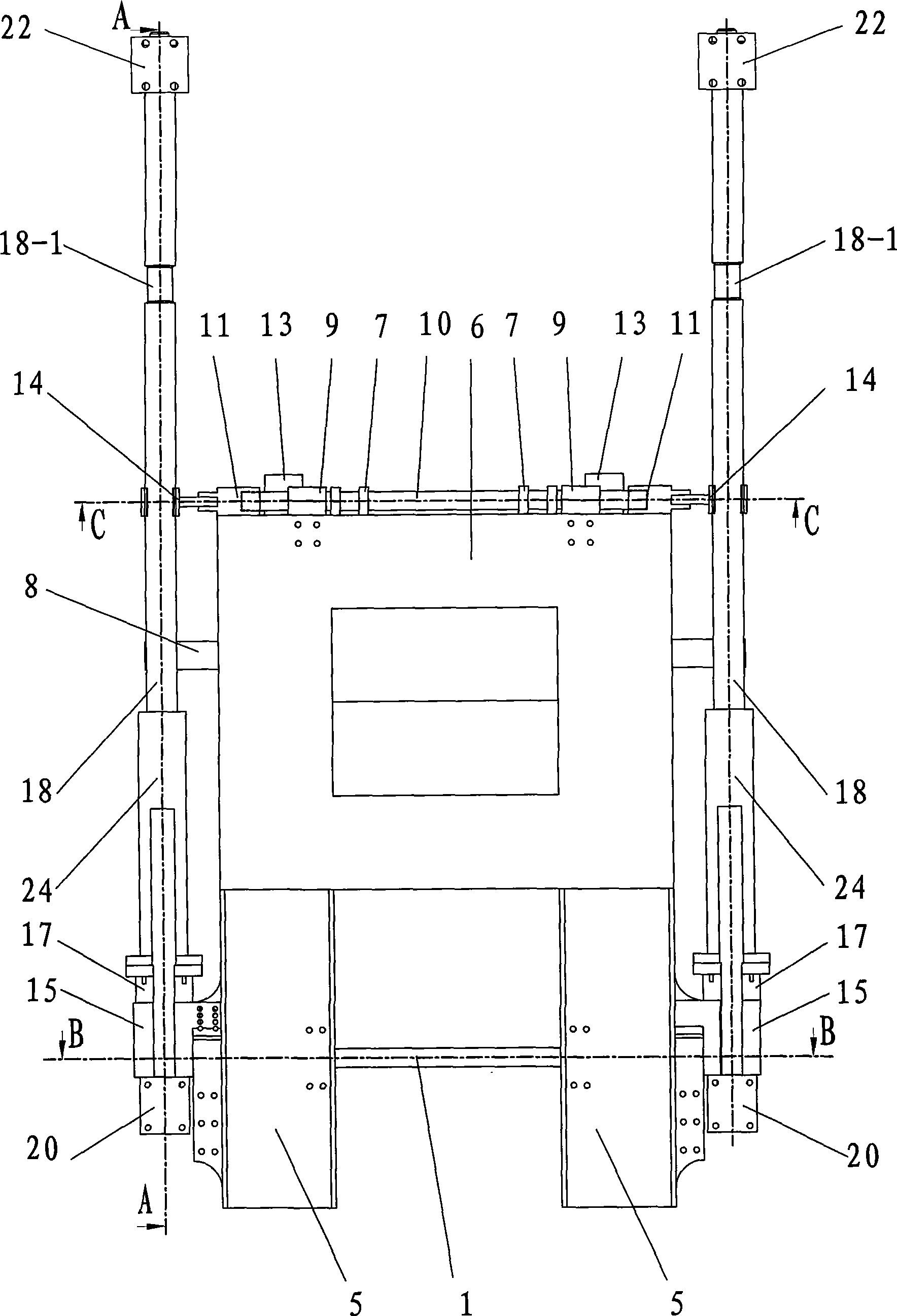
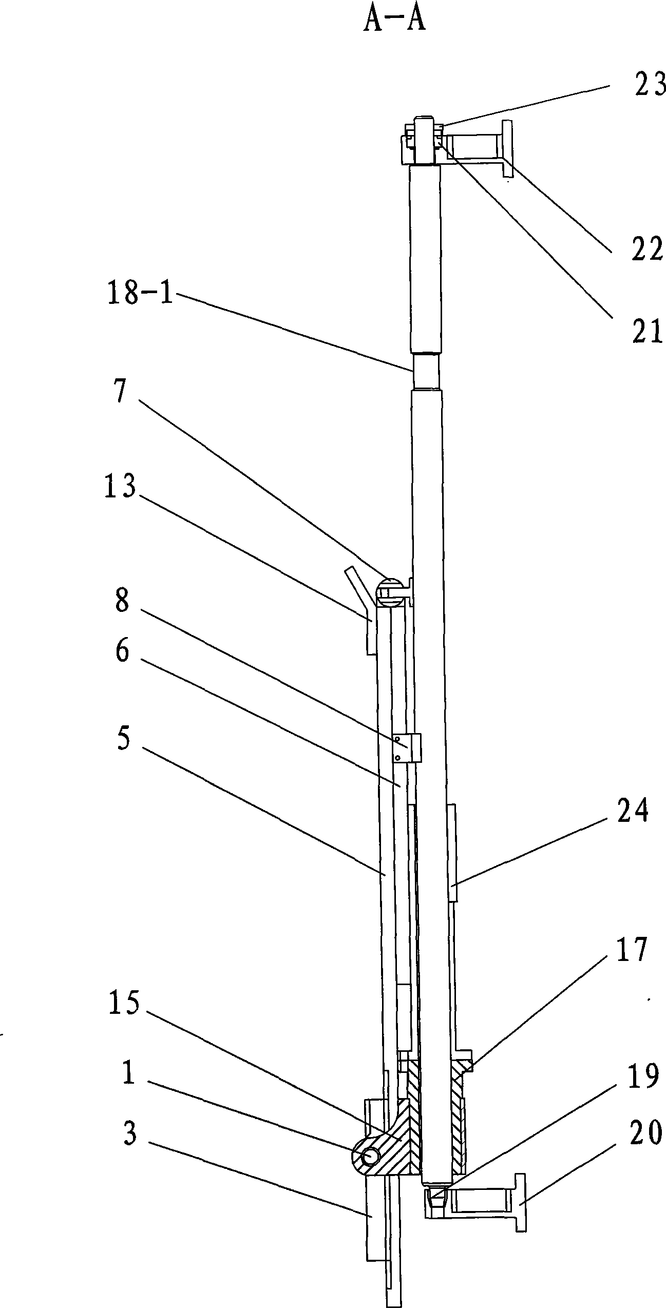
[0008] Specific implementation mode one: combine Figure 1 ~ Figure 4 Describe this embodiment, the vertical lift type lunar rover release mechanism of this embodiment is composed of a screw drive part, a casing part, a display board and a locking and unlocking part, and the screw drive part is fixed by two lead screws 18 and two bearings Nut 23, two bearings 21, two upper bearing seats 22, two bearing bushes 19 and two lower bearing seats 20 are formed, and described two leading screws 18 are arranged vertically in parallel, and the top of each leading screw 18 is all opened with Light groove 18-1, the upper end of each leading screw 18 is all installed on the upper bearing seat 22 through bearing 21 and bearing fixing nut 23, and the lower end of each leading screw 18 is all installed on the lower bearing seat 20 through bearing bush 19; The casing part is composed of two upper casings 24, two middle casings 17, two lower casings 15 and the rear axle 1, and the lower part of...

specific Embodiment approach 2

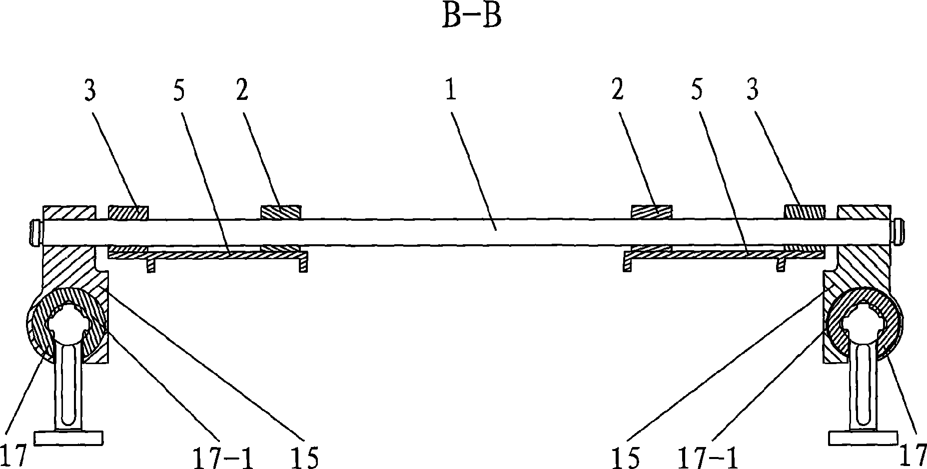
[0009] Specific implementation mode two: combination image 3 To describe this embodiment, the middle casing 17 of this embodiment is provided with a plurality of dust-proof grooves 17-1. With such a setting, it is realized that there is no jamming in the case of dust, and it still works normally. Other components and connections are the same as those in the first embodiment.

[0010] Working principle of the present invention: (see Figure 1 to Figure 7 ) initial position, the long plate 5 and the short plate 6 are in the folded state, the short plate 6 is located on the inner side of the long plate 5, and the unlocking button 14 is buckled on the lead screw 18 to realize the locking function; the lead screw 18 drives the casing part to move upward, The display board and the locking and unlocking part will also move upwards along the leading screw 18. At the light groove 18-1 of the leading screw 18, by the action of the torsion spring 7 mounted on the rear axle 1, the unlo...


PUM


Abstract

The invention relates to a lunar rover release mechanism, in particular to a lunar rover release mechanism of a vertical elevating type, solving the problems that the prior lunar rover release mechanism has the defects of higher slideway processing precision, easy deformation, low release height, low rigidity, multiple degree of freedom and complicated structure, and a locking and unlocking mechanism needed between a lunar rover and a mechanical arm causes greater power consumption. An upper shell and a middle shell are sequentially sleeved on either screw, the lower end of a long plate is mounted on a rear shaft, a short plate limit folded plate is mounted on the outer side surface of the long plate, and two shaft end covers are mounted at the upper end of the long plate and respectively buckled at both ends of a front shaft; one end of one unlocking button and one end of the other unlocking button are respectively mounted on two end surfaces of the two shaft end covers, the other end of one unlocking button and the other end of the other unlocking button are respectively buckled on the two screws, and two short plate connecting sleeves are mounted at the upper end of the short plate and sleeved on the front shaft. The invention has the advantages of high release height, good rigidity, simple structure, little power consumption, and the like.

Description

technical field [0001] The invention relates to a lunar rover release mechanism, which belongs to the technical field of aerospace. Background technique [0002] Whether the lunar rover can be released safely will directly determine the success of this lunar exploration program, so the release mechanism is one of the important devices for the lunar rover to achieve a soft landing on the surface of the moon. At present, during the technical demonstration process of the second phase of the lunar exploration project, relevant domestic departments have proposed a preliminary plan for the leg-type release structure. And the weight is small enough, the strength and rigidity are high enough, it has good environmental adaptability and compatibility with the lunar rover equipment environment. [0003] The currently developed lunar vehicle release mechanisms include pop-up release mechanisms, folding release mechanisms and swing arm release mechanisms. The machining accuracy of the ...

Claims


Application Information

Patent Timeline
Patent Type & Authority Applications(China)
IPC IPC(8): B64G1/16
Inventor 刘荣强周安亮焦震罗昌杰刘飞
Owner HARBIN INST OF TECH
Why Eureka
Try Eureka