
Wireless communication network transmission structure and method

A wireless communication network and transmission system technology, applied in the field of beacon transmission transmission system, can solve the problems of power consumption burden, deterioration of energy efficiency, impracticality, etc., to improve energy efficiency and service life, eliminate useless energy, principle novel effects

Inactive Publication Date: 2010-09-29
TSINGHUA UNIV
View PDF0 Cites 0 Cited by
  • Summary
  • Abstract
  • Description
  • Claims
  • Application Information

AI Technical Summary

Problems solved by technology

For the latter type of events, the current scheme basically adopts the method of blind reception by the receiver, which brings a huge burden on power consumption
During the time period when the receiver receives blindly but the sender does not act, the energy consumed by the node is useless energy, which greatly deteriorates the energy efficiency
Some designs have also taken measures to enable the operation of blind receiving and listening only at certain moments, or reduce the duty cycle of the listening operation, etc., to obtain a small improvement in power consumption and energy efficiency, but it will make the The response time of the beacon frame is prolonged, and there is even the possibility of missing the beacon frame
These methods are impractical and unreliable in networks where emergency wake-up is required

Method used


Image

  • Wireless communication network transmission structure and method
  • Wireless communication network transmission structure and method
  • Wireless communication network transmission structure and method

Examples


Embodiment Construction

[0026] The specific implementation manners of the present invention will be further described in detail below in conjunction with the accompanying drawings and embodiments. The following examples are used to illustrate the present invention, but are not intended to limit the scope of the present invention.

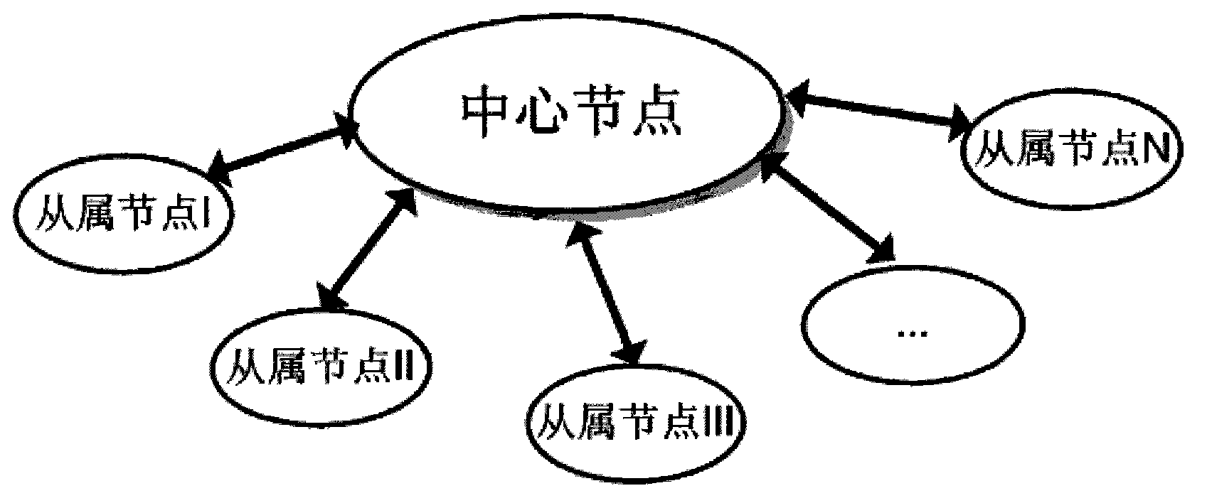
[0027] like figure 1 Shown is a schematic diagram of a communication system of a traditional star network. In the communication system of the traditional star network, a single channel is used between the central node and the slave nodes, and both general data and beacons are transmitted in this channel, and no energy transmission is performed.

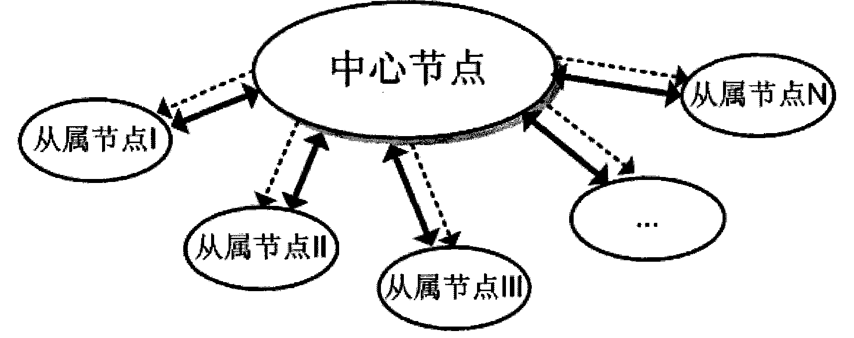
[0028] like figure 2 Shown is a schematic diagram of a communication system in one embodiment of the present invention. In this embodiment, by introducing an auxiliary channel (such as figure 2 Indicated by the dotted arrow in ), separate the data communication and beacon communication between the central node and the slave ...


PUM


Abstract

The invention discloses a wireless communication network transmission structure comprising a main channel for transmitting data between a center node and a slave node and an auxiliary channel for tranThe invention discloses a wireless communication network transmission structure comprising a main channel for transmitting data between a center node and a slave node and an auxiliary channel for transmitting beaconing from the center node to the slave node, wherein the matched auxiliary node is started up according to a beaconing frame signal after the receiving end of the auxiliary channel receismitting beaconing from the center node to the slave node, wherein the matched auxiliary node is started up according to a beaconing frame signal after the receiving end of the auxiliary channel receives the beaconing frame signal sent from the center node. In the communication process of the transmission structure, the event-driven achieved by a beaconing frame replaces a blind receiving action ives the beaconing frame signal sent from the center node. In the communication process of the transmission structure, the event-driven achieved by a beaconing frame replaces a blind receiving action in channel receiving, the inefficient energy consumed by the slave node in the blind receiving process is eliminated, the energy efficiency and the service life of the transmission structure are improvn channel receiving, the inefficient energy consumed by the slave node in the blind receiving process is eliminated, the energy efficiency and the service life of the transmission structure are improved.ed.

Description

technical field [0001] The invention relates to the field of wireless communication, in particular to a transmission system and method for beacon transmission in a star topology wireless communication network. Background technique [0002] At present, the network of star topology and master-slave structure widely appears in many applications such as wireless sensor network and human body wireless sensor network. In applications where the volume and energy of each node device in the network are strictly limited, it is necessary to improve energy efficiency as much as possible, that is, to make every part of energy consumption effective, thereby prolonging the service life of node devices. The resource constraints of the central node are relatively loose, so the slave nodes with strictly limited resources become the focus of optimization. [0003] In communications, beaconing is a very energy-inefficient class of operations. In a conventional communication scheme, the receiv...

Claims


Application Information

Patent Timeline
Patent Type & Authority Patents(China)
IPC IPC(8): H04W52/02H04W84/00
CPCY02B60/50Y02D30/70
Inventor 张晓昱姜汉钧张春谢翔王志华石崇源
Owner TSINGHUA UNIV
Learn More