Trochanter retention plate

A rotor, retention technology, applied in the direction of outer plate, retainer, inner retainer, etc., can solve the problem of material failure, not showing sufficient stability, etc.

Inactive Publication Date: 2009-09-02
SWISSMEDTECHSOLUTIONS
View PDF0 Cites 10 Cited by
  • Summary
  • Abstract
  • Description
  • Claims
  • Application Information

AI Technical Summary

Problems solved by technology

Many of the grafts mentioned have not shown sufficient stability in clinical and / or biomechanical studies, or many of the grafts mentioned have suffered material failure during dynamic loading

Method used


Image

  • Trochanter retention plate
  • Trochanter retention plate
  • Trochanter retention plate

Examples


Embodiment Construction

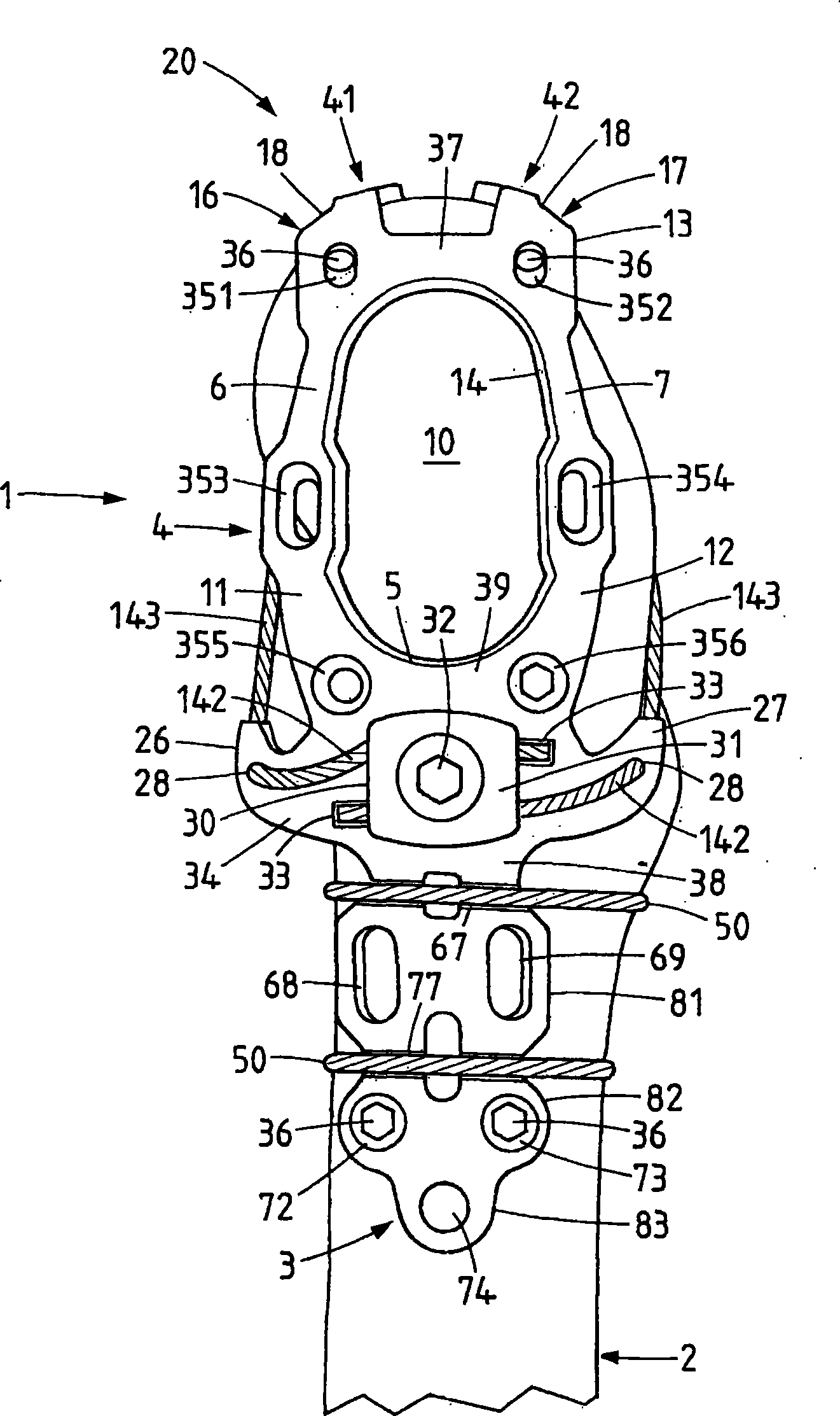
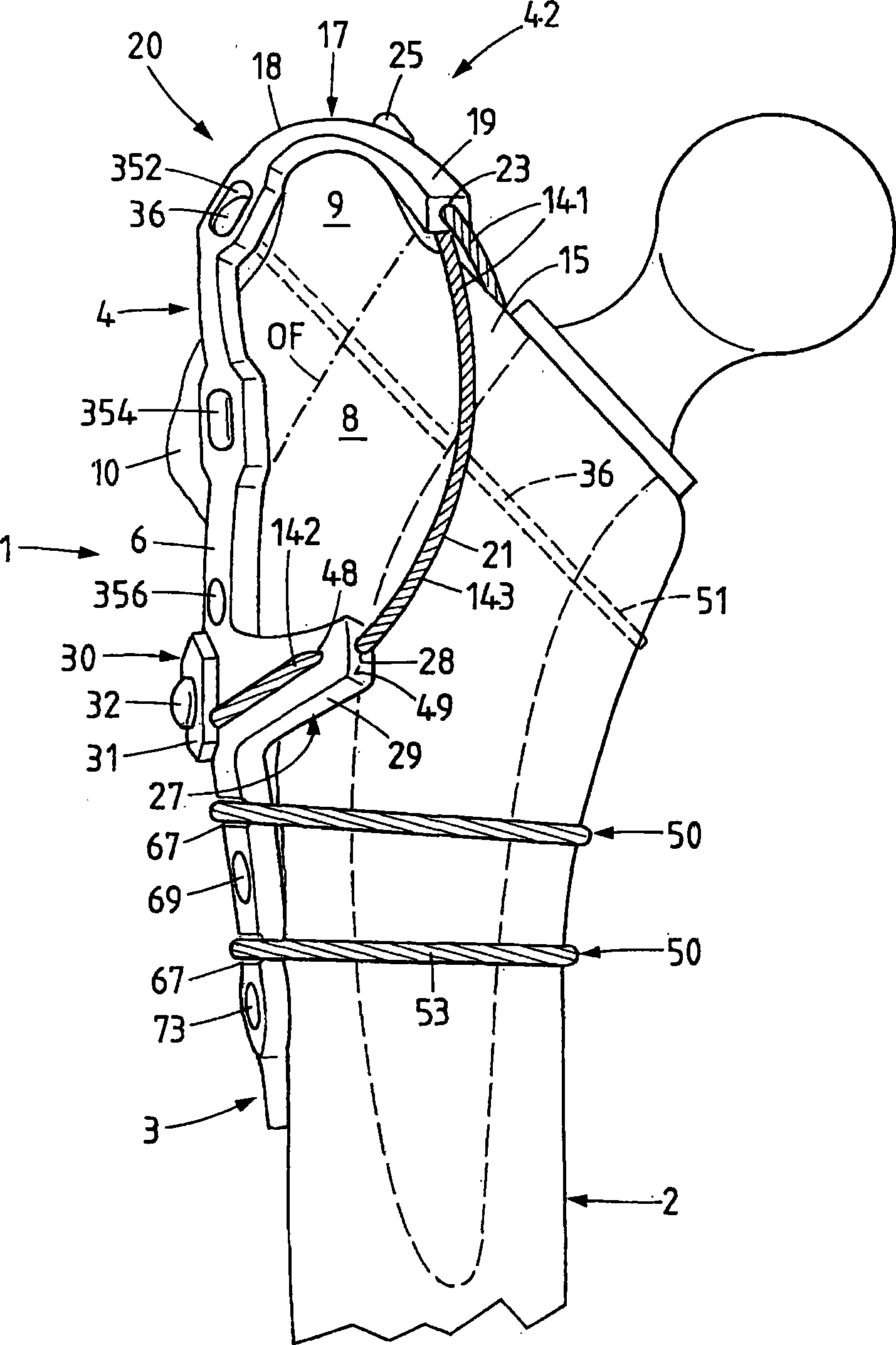
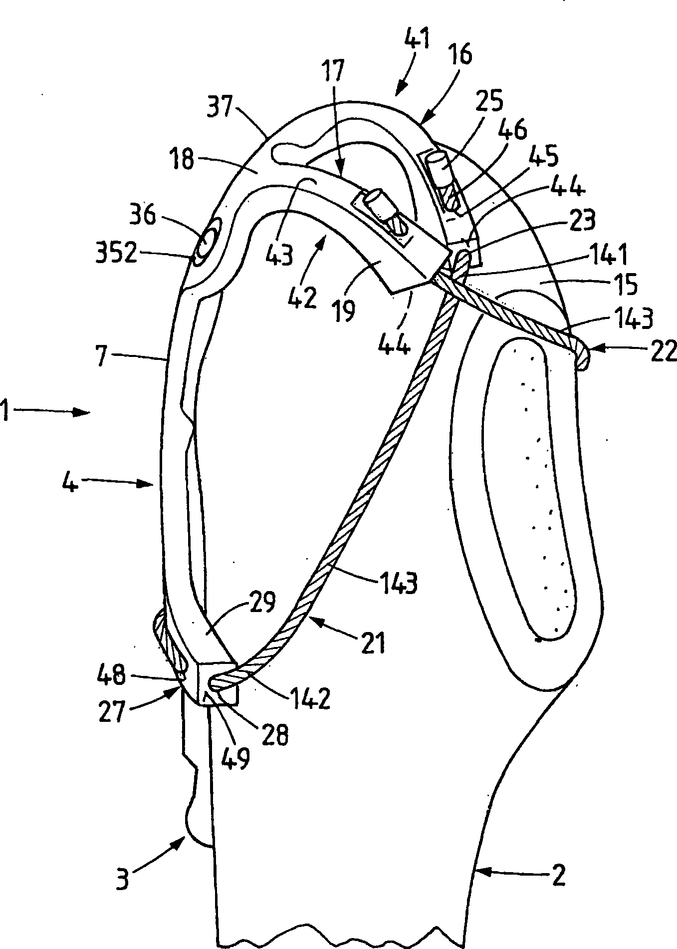
[0033] As stated above and below, the trochanter retention plate, also referred to simply as an implant, is used, among other things, for the anatomical reduction and stable fixation of the greater trochanter 9 on the proximal femur 2 after osteotomy or fracture. figure 2 The osteotomy or fracture plane of the greater trochanter segment is shown at "OF". The plane shown corresponds substantially to a standard osteotomy. For a complete osteotomy, the osteotomy line will define a plane with approximately the same starting point leading further distally. For a so-called Extended Trochanteric Osteotomy (ETO), the osteotomy line will still be directed substantially further distally until entering the proximal femur.

[0034] In the example of embodiment shown, the invention is implemented with two retainers based on the tension band principle, resulting from the combination of lateral horizontal plates and inward horizontal retainers.

[0035] The implant according to the first ...


PUM


Abstract

The invention relates to an implant for refixation of the greater trochanter (9) on which an osteotomy has been performed or which is fractured. The implant comprises a plate (1) that can be fixed on The invention relates to an implant for refixation of the greater trochanter (9) on which an osteotomy has been performed or which is fractured. The implant comprises a plate (1) that can be fixed onthe proximal femur, and a device (20) that can hold the greater trochanter (9) with a form fit or force fit on the femur (2). This holding device (20) preferably has bendable prongs (16, 17) located athe proximal femur, and a device (20) that can hold the greater trochanter (9) with a form fit or force fit on the femur (2). This holding device (20) preferably has bendable prongs (16, 17) located at a distance from each other, the first end portion of these prongs (16, 17) being attached to the upper edge (37) of the base plate (1). The holding device (20) also has flexible, elongate members (2t a distance from each other, the first end portion of these prongs (16, 17) being attached to the upper edge (37) of the base plate (1). The holding device (20) also has flexible, elongate members (21, 22), each of which is attached at one end to the free end portion (19) of the respective prong (16, 17). The other, free end portions (142) of the longitudinal members (21, 22) are secured laterall1, 22), each of which is attached at one end to the free end portion (19) of the respective prong (16, 17). The other, free end portions (142) of the longitudinal members (21, 22) are secured laterally on the base plate (1) after these longitudinal members (21, 22) have crossed the medial aspect of the greater trochanter. This results in a tensioning band construction with at least two restraintsy on the base plate (1) after these longitudinal members (21, 22) have crossed the medial aspect of the greater trochanter. This results in a tensioning band construction with at least two restraintsbased on a plate fixed securely on the proximal lateral femur.based on a plate fixed securely on the proximal lateral femur.

Description

technical field [0001] The present invention relates to an implant for refixing an osteotomized or fractured greater trochanter, a so-called trochanter retention plate, and to a graft for surgically refixing an osteotomized osteotomy using a trochanter retention plate. approach of the or fractured greater trochanter. Background technique [0002] Since the widespread adoption of hip endoprostheses in the 1950s and 1960s, various access approaches to the hip joint have been developed, among them osteotomy of the greater trochanter with subsequent refixation. Refixation of this important tendon of the gluteus medius and minimus as well as the different external rotators should be achieved anatomically after implantation of the prosthesis. Furthermore, the refixation of this important tendon should be withstanding the tension of the abductor muscles, which in certain cases can be equal to three times the body weight. For this purpose, various techniques have been developed. ...

Claims


Application Information

Patent Timeline
Patent Type & Authority Applications(China)
IPC IPC(8): A61B17/80A61B17/82A61B17/84A61B17/74
CPCA61B17/8085A61B17/74A61B17/842A61B17/82A61B17/8061A61B2090/037
Inventor K-U·洛伦兹H·德斯特M·库斯特
Owner SWISSMEDTECHSOLUTIONS
Why Eureka
Try Eureka