
Eureka
For R&D, Eureka makes reading and utilizing patents & technical documents easy.
Eureka AIR
Designed for self-driven R&D workflows. Generate viable solutions, solve complex R&D challenges, empower your innovation with AI.

Eureka Materials
Designed for material experts only. Revolutionize your material R&D, from search, analyze, to developing new materials.

TechResearch
Generate reliable direction feasibility study reports for your R&D in just a few steps.

TechSeek
Discover and master advanced knowledge NOW. Basics, ideas, possibilities, all at once.

TechMind
As an expert in R&D Theories, TechMind can generates customized viable solutions instantly.

TechRisk
Analyze your overall solution with one click, know your potential R&D risks in advance.

TechMonitor
Get weekly tech updates, stay abreast of the latest tech innovations and key insights.
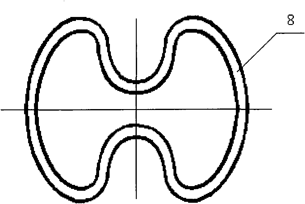
Method for molding expandable bellows
A forming method and corrugated pipe technology, applied in the field of expandable pipe preparation, can solve the problems of large rebound, complex on-site operation, high production cost, etc., and achieve high internal pressure resistance, large external extrusion strength, and high internal pressure resistance intensity effect
- Summary
- Abstract
- Description
- Claims
- Application Information
AI Technical Summary
Problems solved by technology
Method used
Image


Examples
Embodiment Construction
[0026] Below in conjunction with embodiment, further illustrate the present invention.
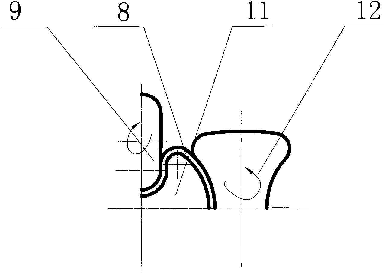
[0027] The steps of the forming method of the present invention are as follows: figure 2 Shaping method shown:
[0028] (1) At first take the 15# steel garden pipe 1 of the required length, diameter and wall thickness to be processed.
[0029](2) In the preforming area, move the round tube 1 axially at a constant speed at a speed of 0.5m / min, and heat it to 700°C. Use preforming roller I group (consisting of left preforming roller 2 and right preforming roller 6, the rollers are the waist drum type, left and right symmetrical) and preforming roller II group (consisting of upper preforming roller 4 and lower preforming roller) Roller 5 forms, and roller is described discus shape, and up and down symmetry) is arranged on the left and right upper and lower positions of garden pipe 1 cross-section and bellows is carried out preforming. Wherein garden pipe is supported by track, and two gro...
PUM
 Abstract
Description
Claims
Application Information
 - R&D Engineer
- R&D Manager
- IP Professional
- Industry Leading Data Capabilities
- Powerful AI technology
- Patent DNA Extraction
Browse by: Latest US Patents, China's latest patents, Technical Efficacy Thesaurus, Application Domain, Technology Topic, Popular Technical Reports.
© 2024 PatSnap. All rights reserved.Legal|Privacy policy|Modern Slavery Act Transparency Statement|Sitemap|About US| Contact US: help@patsnap.com