Subassembly for sliding roof

A component and component technology, applied in the field of sub-components, can solve problems such as complex structure, inability to shift, and guide rails that should not be tilted

Inactive Publication Date: 2009-09-09
ROOF SYST GERMANY
View PDF1 Cites 7 Cited by
  • Summary
  • Abstract
  • Description
  • Claims
  • Application Information

AI Technical Summary

Problems solved by technology

[0002] The problem with such a part is that it should not be tilted in the rails
Second, the part does not shift smoothly within the rails
The structure is relatively complex due to the large number of diverting pulleys

Method used


Image

  • Subassembly for sliding roof
  • Subassembly for sliding roof
  • Subassembly for sliding roof

Examples


Embodiment Construction

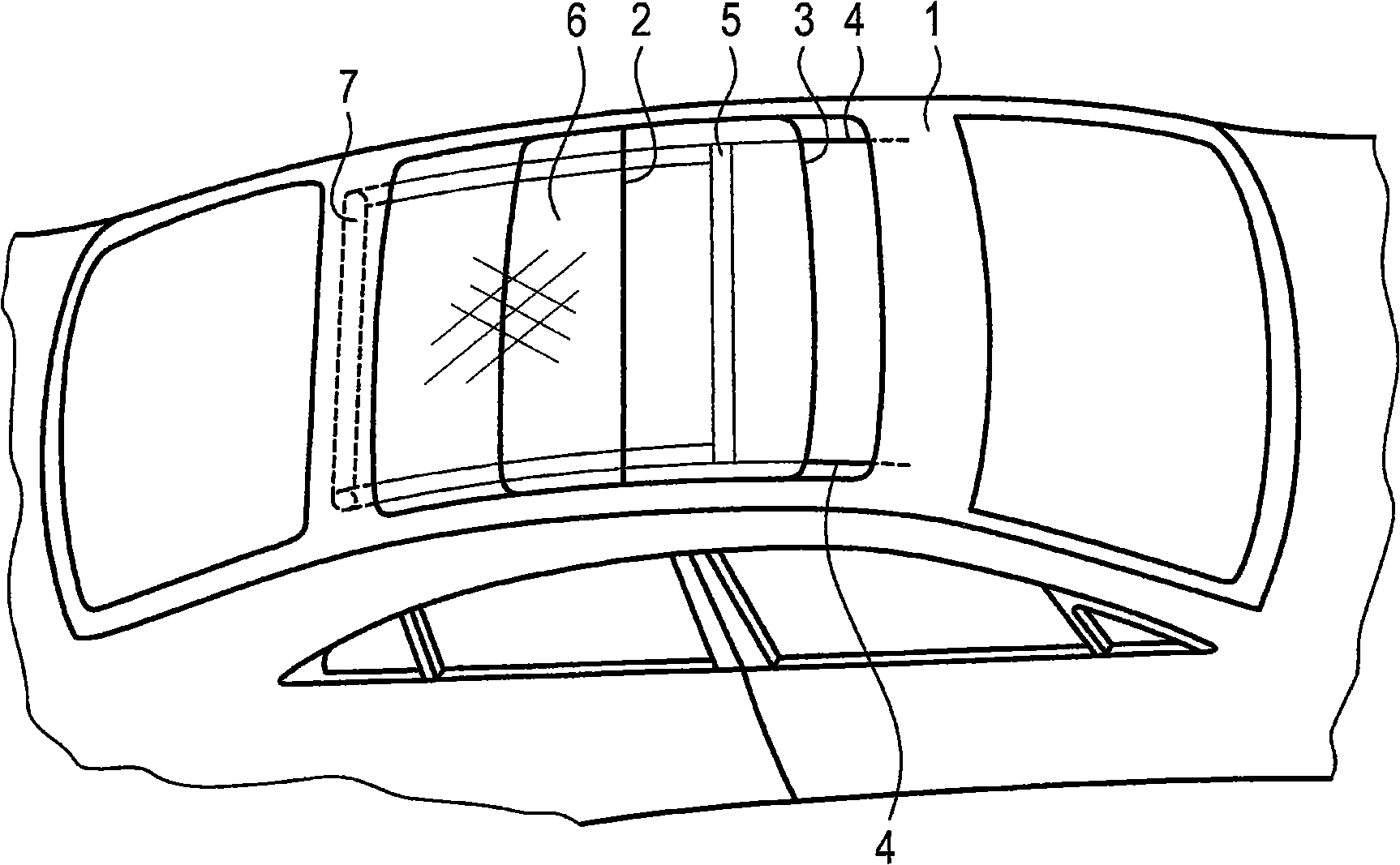
[0020] figure 1 A roof 1 of a motor vehicle is shown schematically, which is equipped with a sliding roof. The sliding roof has a rear cover part 2 and a front cover part 3 , the front cover part being shown in a partially pushed back position, wherein it overlaps the rear cover part 2 . The cover 3 serves to partially or completely open a roof opening formed in the roof 1 . Between a pushed back position (wherein the bow is at the rear) and a pulled forward position (wherein the bow is at the front and the roller blind sheet 6 provides shade for the interior) the sunshade roller blind can be positioned on the cover shift down.

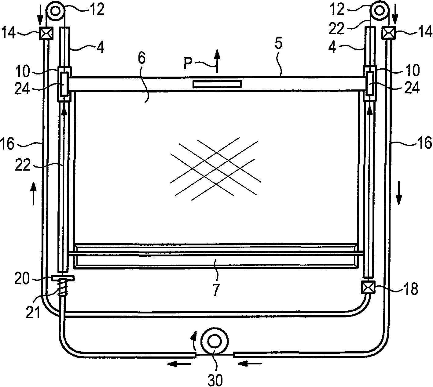
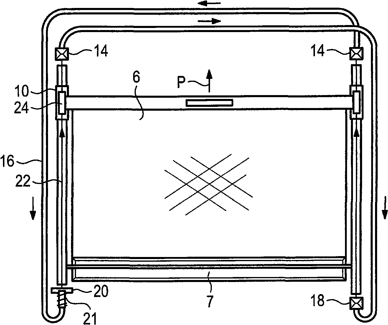
[0021] To this top 1 are attached rails 4 to which a cover 3 can be displaceably attached. A component 5 is displaceably guided in the guide rail 4 , which in the exemplary embodiment shown here is a bow of a roller blind. The roller sunshade comprises a roller blind 6 extending between a bow 5 and a roller shaft 7 arranged at the rear, the bow be...


PUM


Abstract

A subassembly for a sliding roof includes right and left guiderails, which lie opposite each other. A component extends between the left and right guiderails and is guided therein. A cable includes a first section that extends between a right front side of the component and a left rear side of the component. The cable also includes a second section that extends between a left front side and a right rear side. Some sections of the cable are guided in a Bowden cable sheath.

Description

technical field [0001] The invention relates to a subassembly for a sliding roof, in particular with a part guided displaceably in two opposite guide rails. For example, the component can be a roller sunblind or otherwise a cover. Background technique [0002] The problem with this type of part is that it should not tilt in the rails. Second, the part does not displace smoothly within the rails. This problem becomes more pronounced the shorter and smaller the part is when viewed in the direction in which it is displaced. For example, if one considers a bow which, viewed in idealized form, is mounted in a point-like manner within each guide rail, this can be seen as such guides do not offer any protection against tilting . [0003] DE 100 64 718 C1 already discloses a roller sunblind with a bow to which two cables are attached. The latter are guided via a total of 6 deflection pulleys, which prevent tilting of the bow. The structure is relatively complex because of the ...

Claims


Application Information

Patent Timeline
Patent Type & Authority Applications(China)
IPC IPC(8): B60J1/20B60J7/047E05D13/00
CPCB60J7/0015B60J7/0573
Inventor 约阿希姆·勒德尔兹拉特科·赫格尔斯特凡·福格尔
Owner ROOF SYST GERMANY
Why Eureka
Try Eureka