
A system and a method for detecting gas turbine blade or aircraft engine blade problems in real time

A technology of aircraft engines and gas turbines, which is applied in the direction of gas turbine engine testing, machine/engine, engine testing, etc., and can solve problems such as damage, unplanned maintenance, and loss

Inactive Publication Date: 2009-09-09
GENERAL ELECTRIC CO
View PDF0 Cites 24 Cited by
  • Summary
  • Abstract
  • Description
  • Claims
  • Application Information

AI Technical Summary

Problems solved by technology

These failure modes all have the potential to lead to unscheduled repairs if they result in a catastrophic failure such as blade breakage
In addition, they can also cause considerable damage due to the loss of faulty parts that are no longer repairable
The consequential damages and loss of revenue due to the inability of the plant to provide power can be considerable for a power plant operator

Method used


Image

  • A system and a method for detecting gas turbine blade or aircraft engine blade problems in real time
  • A system and a method for detecting gas turbine blade or aircraft engine blade problems in real time
  • A system and a method for detecting gas turbine blade or aircraft engine blade problems in real time

Examples


Embodiment Construction

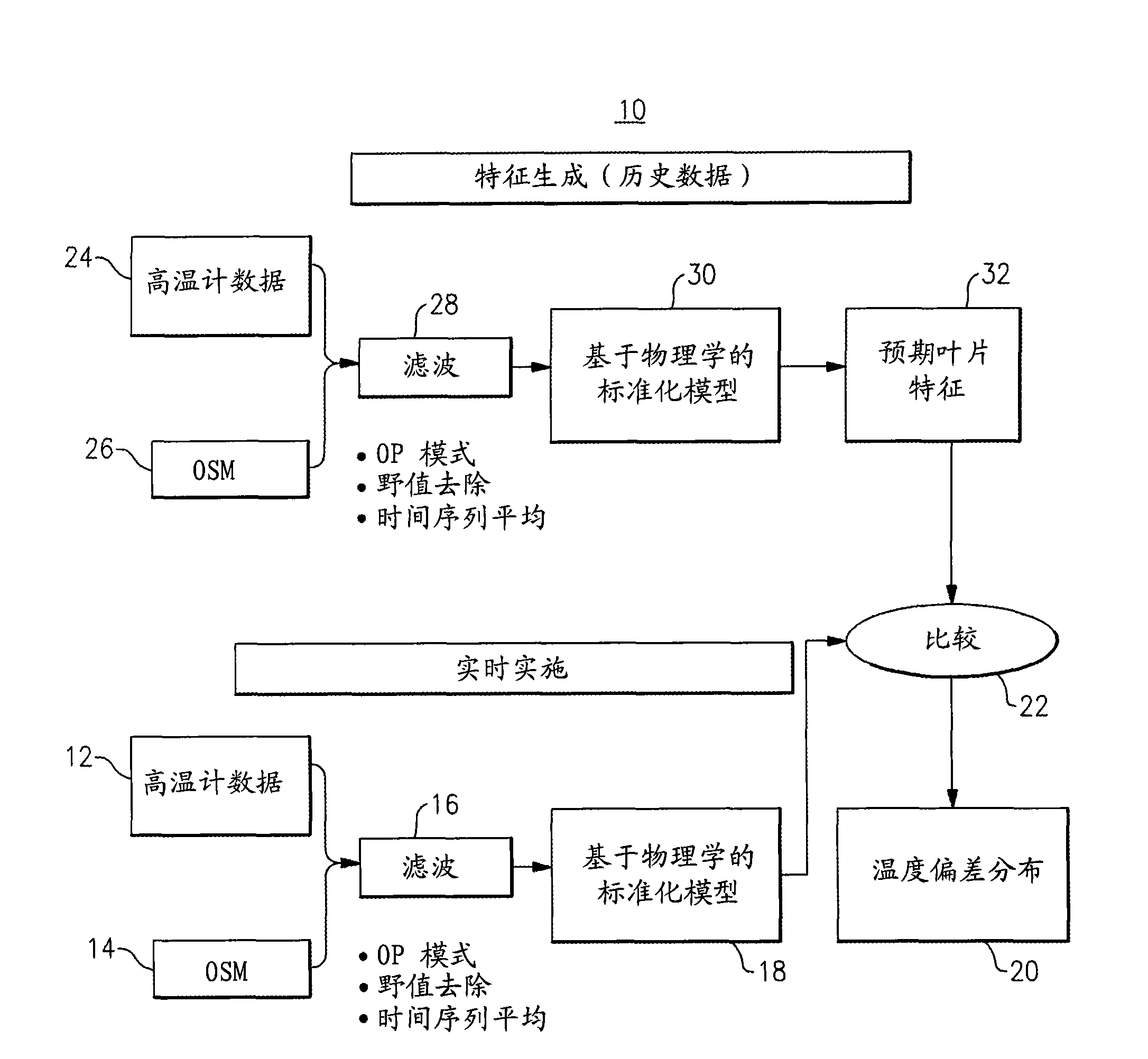
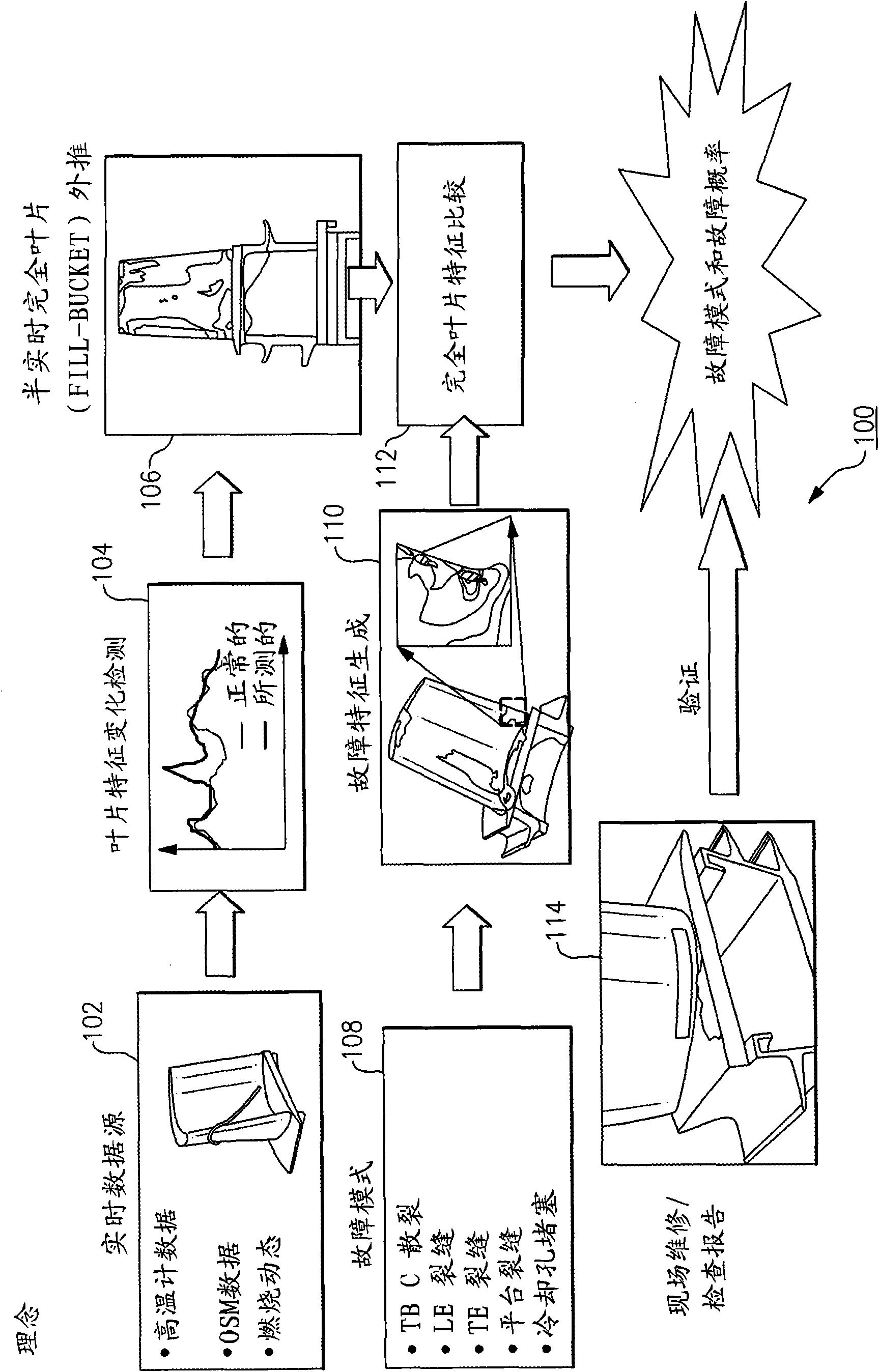
[0016] figure 1 Is a flowchart of a method and system 10 for real-time detection of gas turbine or aircraft engine blade problems according to one embodiment. System 10 may provide a means for real-time detection of gas turbine or aircraft engine blade problems, including, but not limited to, gas turbine or aircraft engine blade failure, when the turbine or aircraft engine is operating using gas turbine or aircraft engine operating data and optical pyrometer data. Thermal barrier coating spalls, cracks, and blocked cooling channels.

[0017] According to one aspect, system 10 utilizes at least one optical pyrometer 12 to generate optical pyrometer data. However, it is difficult to develop a monitoring system based on optical pyrometer data since the absolute temperature value of the blade needs to be known. For example, it is difficult to base the signal acquired by the optical pyrometer 12 with respect to absolute temperature due to emissivity variations and / or blockages wi...


PUM


Abstract

The present invention relates to a method and a system 10 for detecting gas turbine blade or aircraft engine blade problems in real time. The method and system 10 are implemented to detect gas turbine blade or problems in real time and provide more accurate prediction capabilities than known techniques due to inclusion of physics-based correction and temperature modeling methods for the hot gas path parts lifing. The system and method 10 use pyrometer data 12,24 and operational data 14,26 to generate physics-based corrections 18,30 of pyrometer data and physics-based bucket temperature estimations 20 and failure signatures 32.

Description

technical field [0001] The present invention relates generally to gas turbines and aircraft engines, and more particularly to methods and systems for real-time detection of gas turbine blade and aircraft engine problems. Background technique [0002] Gas turbine engines operate at relatively high temperatures. The capacity of such engines is largely limited by the ability of the turbine blade material to withstand the thermal stresses that develop at such relatively high operating temperatures. In industrial gas turbine engines, this problem is particularly acute due to the relatively large size of the turbine blades. [0003] Hollow convection cooled turbine blades are frequently used to accommodate higher operating temperatures and increase engine efficiency without causing blade failure. Such blades typically have internal passageways providing flow passages to ensure efficient cooling, wherein all parts of the blade can be maintained at a relatively uniform temperature...

Claims


Application Information

Patent Timeline
Patent Type & Authority Applications(China)
IPC IPC(8): G01M15/00G01M19/00G01M99/00
CPCF01D17/085F05D2270/112F01D21/003F05B2270/1091F05D2270/70F05B2270/70G01M15/14
Inventor V·B·贾穆S·赖S·巴拉苏布拉马尼安M·K·查蒂O·韦拉甘杜拉N·V·尼尔马兰
Owner GENERAL ELECTRIC CO
Learn More