Physics-Based Lifespan Modeling

Active Publication Date: 2010-06-17
GENERAL ELECTRIC CO
View PDF9 Cites 40 Cited by
  • Summary
  • Abstract
  • Description
  • Claims
  • Application Information

AI Technical Summary

Problems solved by technology

However, a lack of agreement between the predicted lifespan of an engine component and the lifespan observed in the field diminishes the ability of the manufacturer to accurately forecast the actual lifespan of the engine component.
As a result, increased cost to the engine manufacturer, reduced availability of the engine, and reduced revenue to the engine owner may occur.
Poor sensor performance may yield an inaccurate pi

Method used


Image

  • Physics-Based Lifespan Modeling
  • Physics-Based Lifespan Modeling
  • Physics-Based Lifespan Modeling

Examples


Embodiment Construction

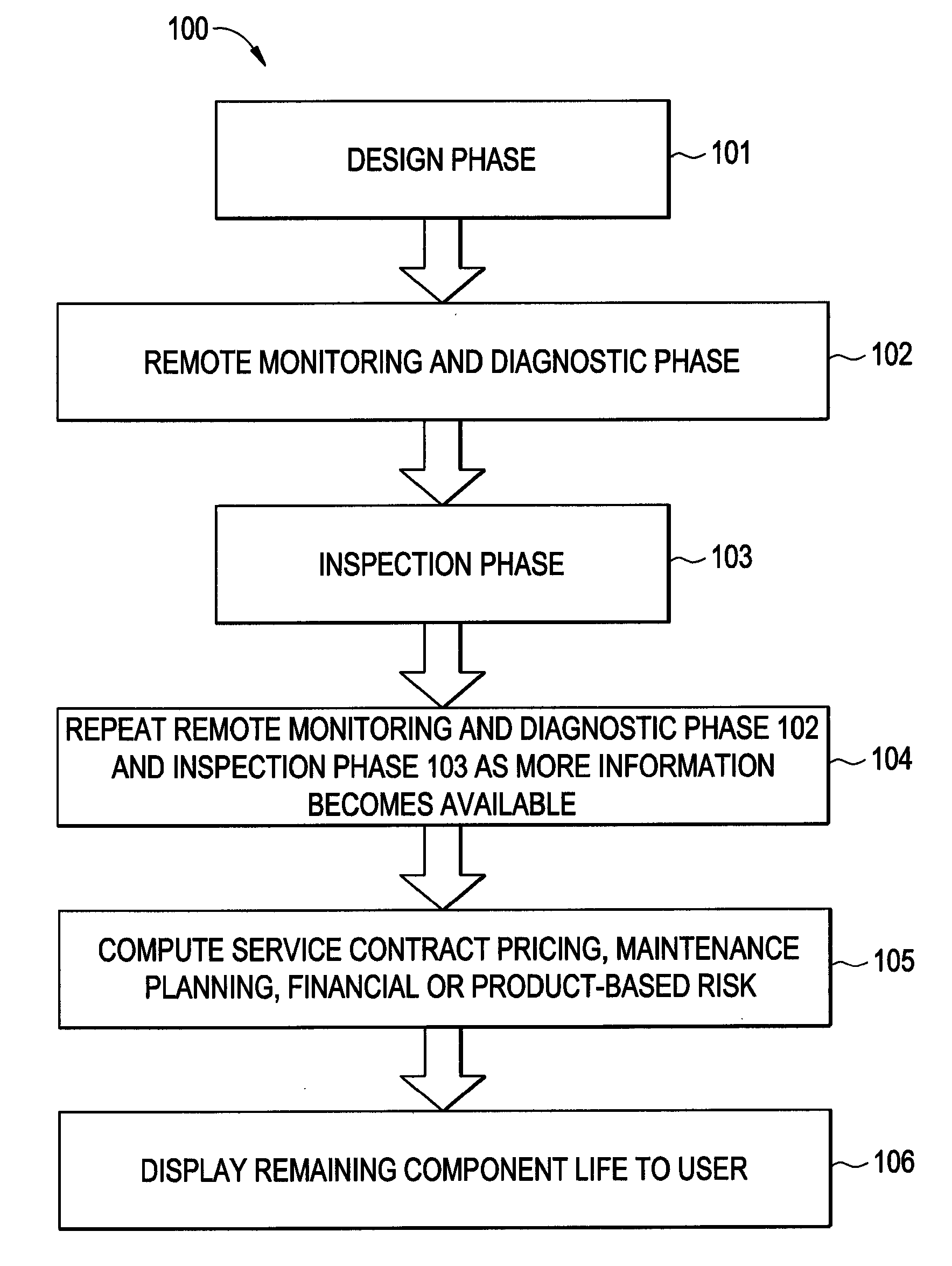
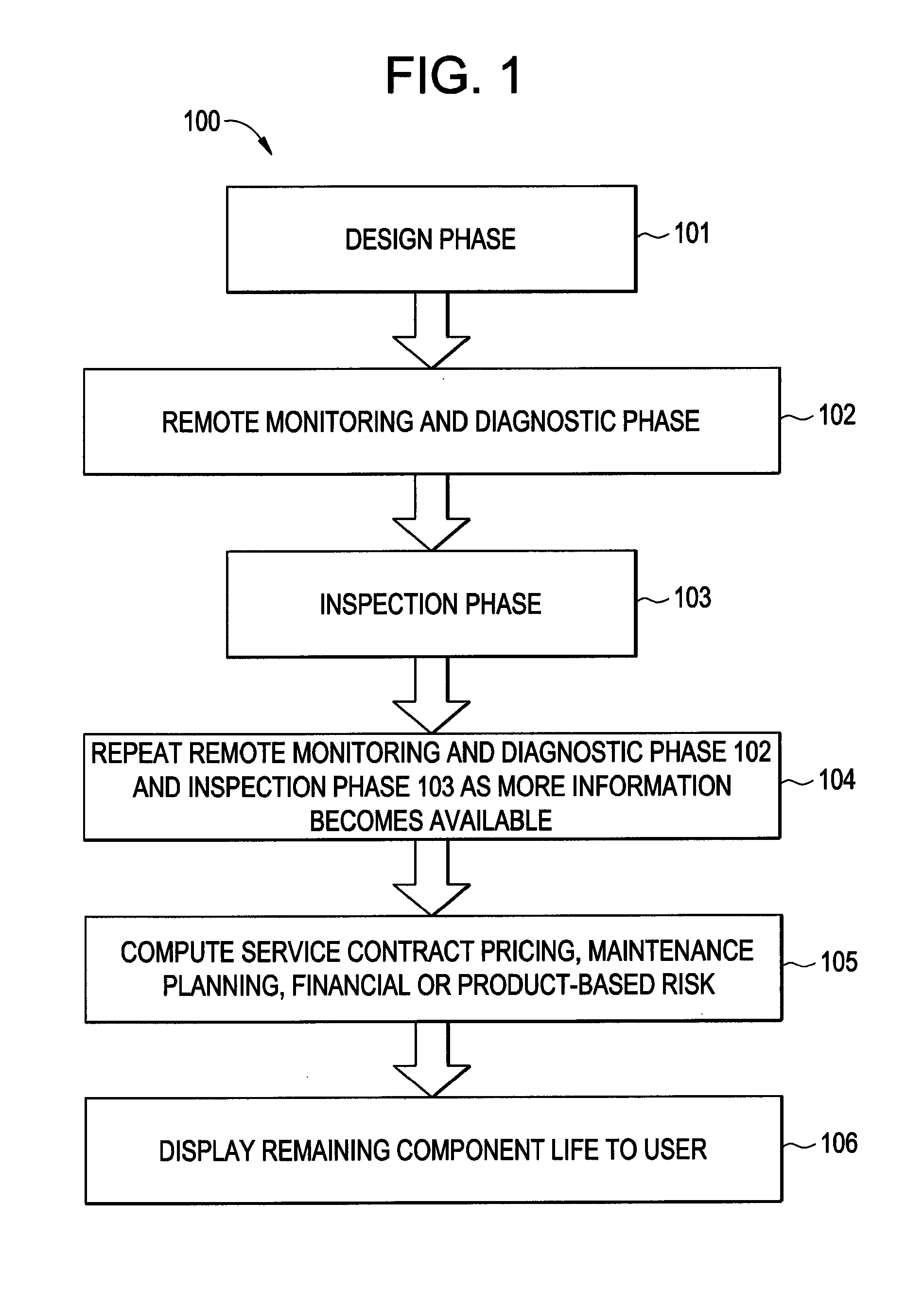
[0015]Lack of agreement between the predicted lifespan of turbine engine components and actual lifespan observed in field operation diminishes the ability of a manufacturer to accurately forecast the lifespan of engine components. Disagreement between design predictions and field data may occur in three scenarios. Design predictions, when they are manipulated probabilistically, may match the observed average behavior of the field data, but not the variation. Alternatively, the probabilistic design predictions may match the field variation, but not the average. Lastly, neither the average nor variation may match the probabilistic design prediction.

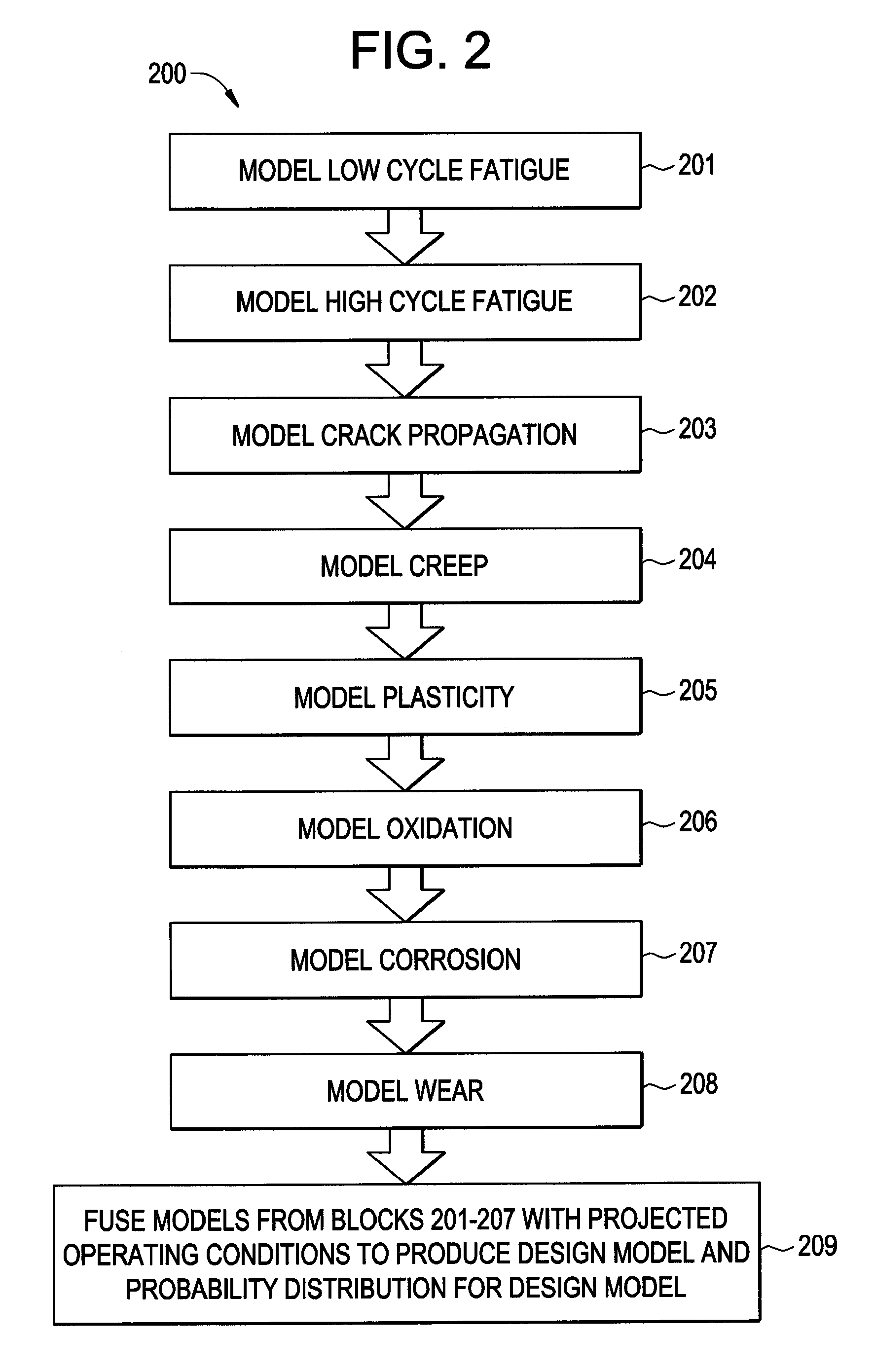
[0016]These mismatches may be due to insufficient physics simulations, or models, of critical variable variations from specific engine operation histories. Design computations and field data each explain some portion of the average lifespan and variation of a component. Through modeling that combines an existing or improved design model in ...


PUM


Abstract

An embodiment of a method for lifespan modeling for a turbine engine component includes determining a design-phase model of the lifespan of an turbine engine component; fusing the design-phase model with sensor data collected during operation of the turbine engine component to produce an updated model of the lifespan of the turbine engine component; and fusing the updated model with data collected during an inspection of the turbine engine component to produce an overall model of the lifespan of the turbine engine component. Systems for lifespan modeling for a turbine engine component are also provided.

Description

BACKGROUND OF THE INVENTION[0001]The present disclosure generally relates to monitoring and maintenance planning for turbine engines.[0002]Accurate and cost-effective maintenance planning for turbine engines, such as aircraft engines, or turbines used for propulsion or power generation, requires precise predictions of the lifespan associated with critical degradation and failure modes of engine components. Existing design and maintenance practices focus on collection of operational, damage, and failure data from various sensors and from inspection of the engine as it operates in the field, and comparing the collected data to lifespan predictions made at the design stage. If the field performance data and predictions do not agree, future maintenance planning of the particular engine is based primarily on the collected field data, with a diminished role given to design stage predictions. Previous field experience with an engine having a similar design may also be used to predict an en...

Claims


Application Information

Patent Timeline
IPC IPC(8): G06G7/64
CPCG05B23/0283
Inventor KHAN, KHAN MOHAMED KHIRULLAH GENGHISALI, MOHAMED AHMEDAYHAN, ALI OSMANBEHERA, AJAY KUMARISBURGH, ANNE MARIEJAMMU, VINAY BHASKARMADELONE, JR., JOHN JOSEPHVELAGANDULA, OMPRAKASH
Owner GENERAL ELECTRIC CO
Why Eureka
Try Eureka