Clamping fixture

A jig and clamping technology, which is applied in the field of clamping jigs for magnetic components, can solve problems such as easy tilting of components

Inactive Publication Date: 2012-03-28
HONG FU JIN PRECISION IND (SHENZHEN) CO LTD +1
View PDF6 Cites 1 Cited by
  • Summary
  • Abstract
  • Description
  • Claims
  • Application Information

AI Technical Summary

Problems solved by technology

In addition, during the movement of the clamping component, due to the small contact surface between the tweezers and the component, the component is prone to tilt during the movement

Method used


Image

  • Clamping fixture
  • Clamping fixture
  • Clamping fixture

Examples


Embodiment Construction

[0011] The present invention will be described in further detail below in conjunction with the accompanying drawings.

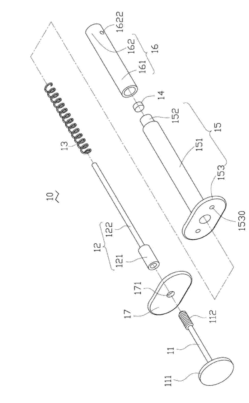
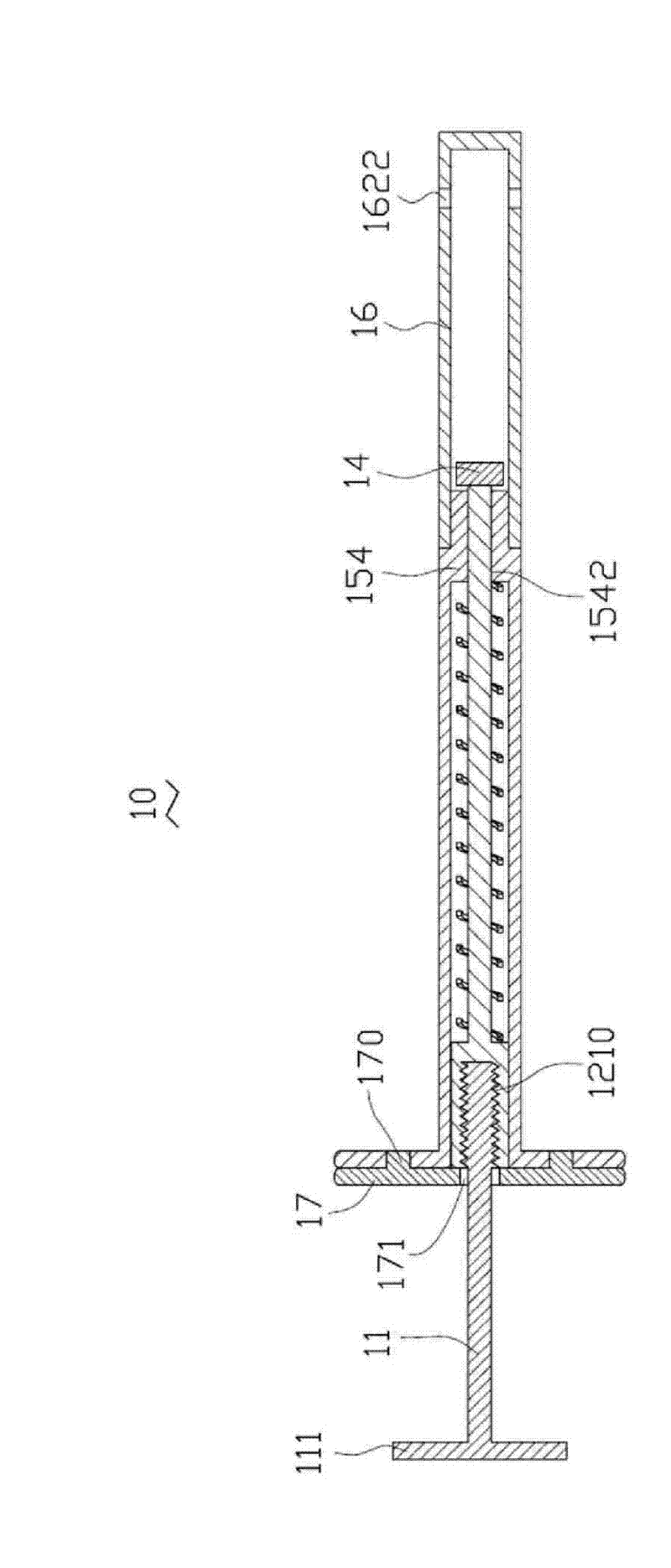
[0012] Such as figure 1 and 2 As shown, it is a clamping jig 10 provided by the first embodiment of the present invention. The clamping fixture 10 includes a force application rod 11 , a guide rod 12 , a spring 13 , a magnet 14 , a first cylinder 15 , a second cylinder 16 and a cover 17 .

[0013] A part of the force applying rod 11 is movably accommodated in the first cylinder 15, and the rest protrudes from the first cylinder 15. Most of the guide rod 12 is movably accommodated in the first cylinder 15, and a small part is accommodated in the first cylinder 15. In the second cylinder 16 , the spring 13 is sleeved on the guide rod 12 and accommodated in the first cylinder 15 , and the magnet 14 is fixed on the end of the guide rod 12 and accommodated in the second cylinder 16 .

[0014] The force applying rod 11 is a cylinder, with a finger portion 111 at...


PUM


Abstract

The invention provides a clamping fixture, which comprises a first cylinder, a second cylinder, a push-pull rod, a spring, a magnet and a cover. The first cylinder is a hollow cylinder with openings at two ends, and comprises a big cylinder and a small cylinder which are concentrically arranged. The joint of the big cylinder and the small cylinder protrudes out of the internal surface of the first cylinder to form a lug boss with a through hole. The second cylinder is a hollow cylinder comprising a connecting end and a clamping end, wherein the connecting end is connected with the small cylinder, and the clamping end is used for clamping objects. The push-pull rod is movably accommodated in the first cylinder and the second cylinder. One end of the push-pull rod forms a finger press part protruding out of the big cylinder. The spring is sleeved on the push-pull rod and accommodated in the first cylinder to provide elastic-restoring force for the push-pull rod to be away from the second cylinder. The magnet is fixed at the other end of the push-pull rod and positioned in the second cylinder and the size of the magnet is more than or equal to that of the through hole. The cover is fixed at one end of the big cylinder near the finger press part so as to prevent the push-pull rod from pulling out of the first cylinder.

Description

technical field [0001] The invention relates to a clamping jig, in particular to a clamping jig for a magnetic element. Background technique [0002] During the clamping process of the magnetic component, tweezers or similar fixtures are often used to clamp the component in the middle of the tweezers. When the magnetic element is placed in a structure that is extremely close to its shape, there is no extra space between the two for tweezers. In order to use the tweezers to hold the magnetic component, it is necessary to provide a space for accommodating the tweezers. In addition, during the movement of the clamping element, since the contact surface between the tweezers and the element is small, the element is prone to tilt during the movement. Contents of the invention [0003] In view of this, it is necessary to provide a clamping fixture that saves space and moves smoothly. [0004] A clamping jig includes a first cylinder, a second cylinder, a push-pull rod, a sprin...

Claims


Application Information

Patent Timeline
Patent Type & Authority Patents(China)
IPC IPC(8): B25B11/00
Inventor 廖家宏
Owner HONG FU JIN PRECISION IND (SHENZHEN) CO LTD
Why Eureka
Try Eureka