Vehicle headlamp

A technology for headlights and vehicles, which is applied to vehicle components, lighting devices, fixed lighting devices, etc., and can solve the problems of high prices of drive motors and electronic components, high manufacturing costs of headlights, etc., and avoid glare and halo phenomena , to achieve the effect of operation reliability and safety

Inactive Publication Date: 2009-09-16
KOITO MFG CO LTD
View PDF1 Cites 18 Cited by
  • Summary
  • Abstract
  • Description
  • Claims
  • Application Information

AI Technical Summary

Problems solved by technology

[0005] However, in the electronically controlled irradiation direction changing mechanism, there is a problem that the co

Method used


Image

  • Vehicle headlamp
  • Vehicle headlamp
  • Vehicle headlamp

Examples


Embodiment Construction

[0028] Next, an embodiment of a vehicle headlamp for carrying out the present invention will be described.

[0029] The vehicle headlamps 1, 1 are attached to both left and right end portions of the front portion of the vehicle body, respectively.

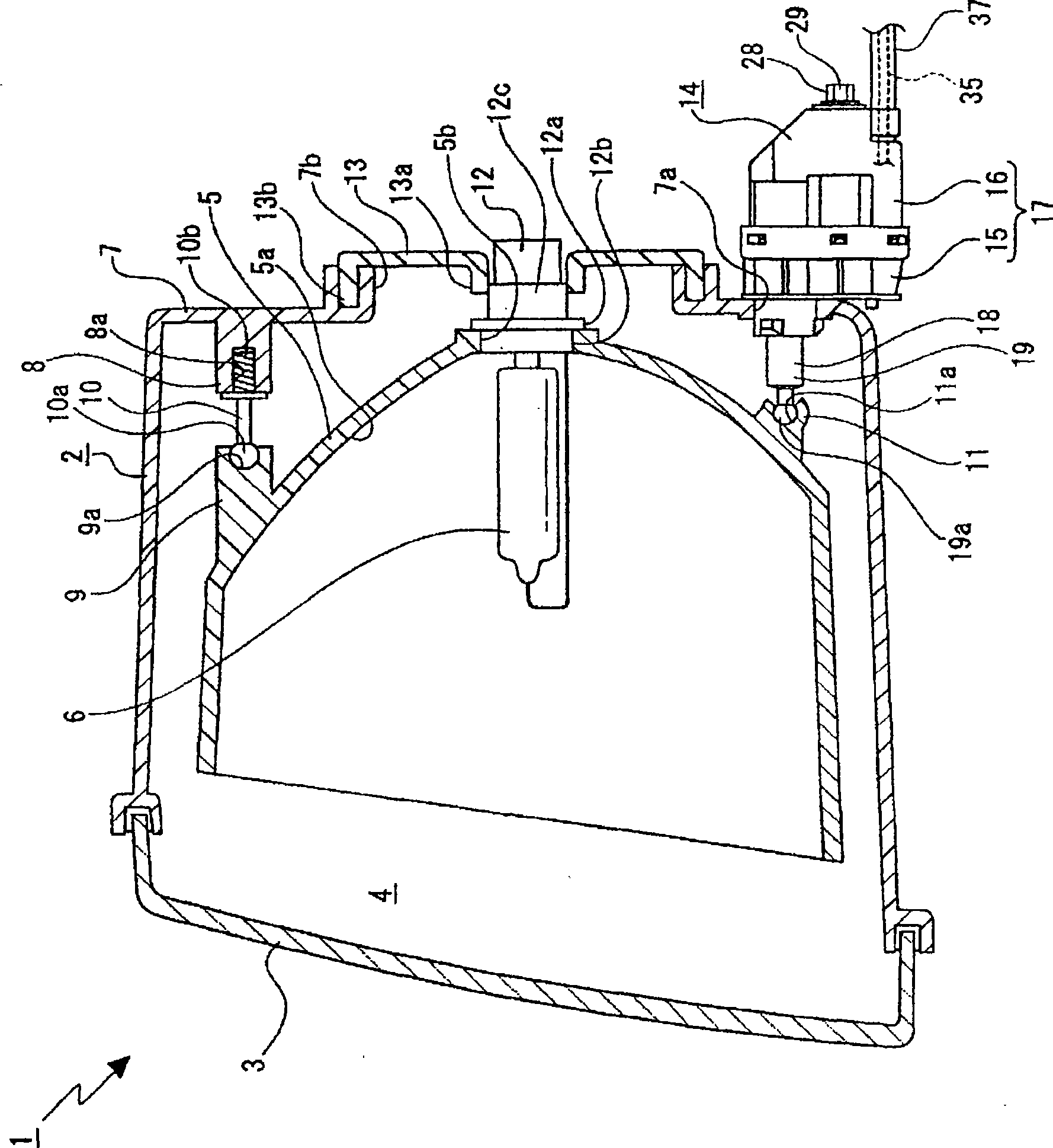
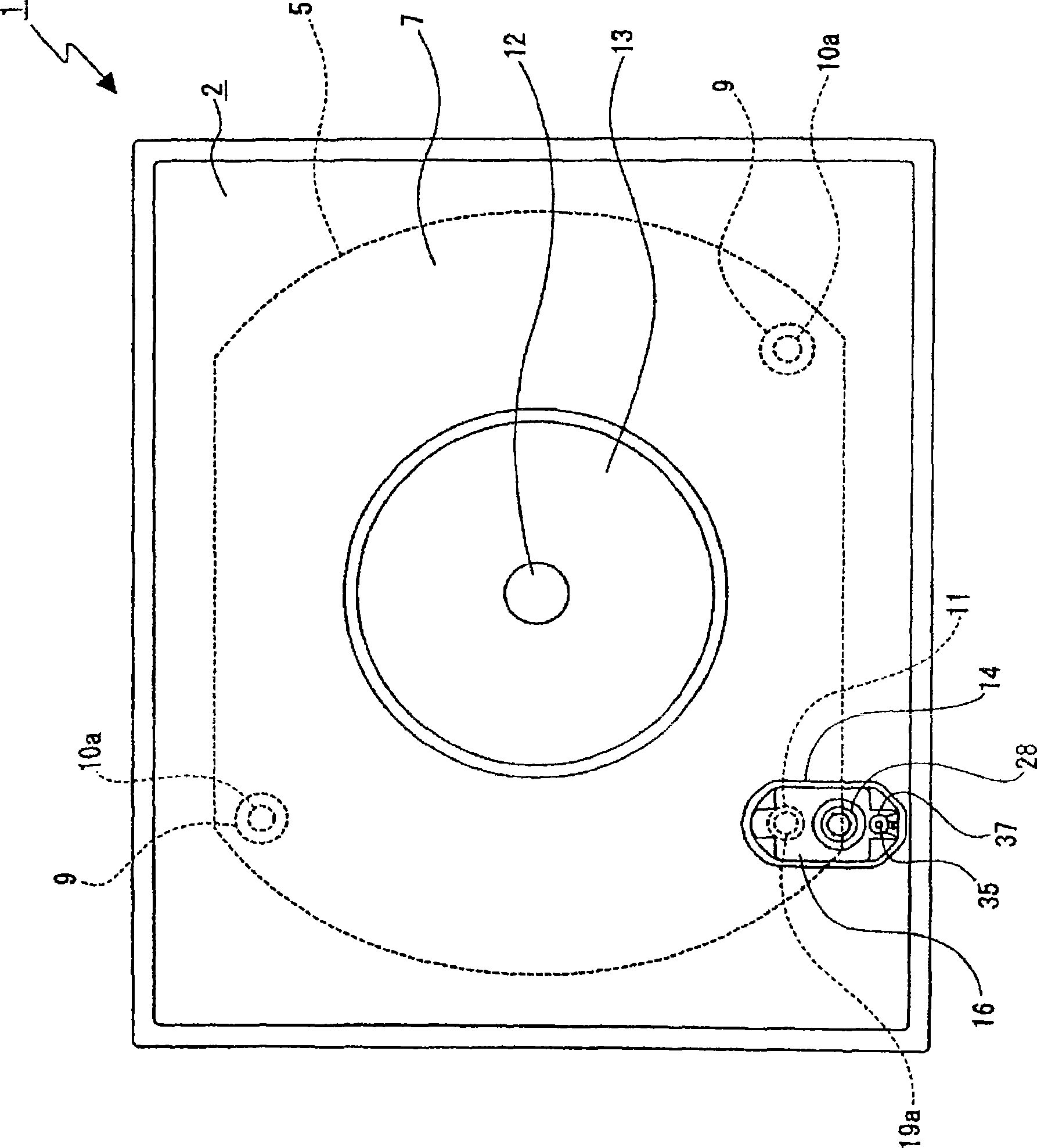
[0030] Vehicle headlamps 1 such as figure 1 As shown, a reflector 5 and a light source 6 installed on the reflector 5 are disposed in the lamp space 4. The lamp space 4 is surrounded by a lamp housing 2 and a lampshade 3, wherein the lamp housing 2 forms The lampshade 3 is in the shape of a container opened forward, and covers the opening of the lamp housing 2 .

[0031] A through hole 7 a is formed on the lower end portion of the rear surface portion 7 of the lamp housing 2 . On the front surface of the rear surface portion 7 of the lamp housing 2, there are provided supporting protrusions 8, 8 protruding forward, and mounting recesses 8a, 8a are formed on the supporting protrusions 8, 8, and the mounting recesses 8a, 8a face fo...


PUM


Abstract

The invention provides a vehicle headlamp, which implementing mechanism simplification on the base of assuring safety and stable supporting condition of reflector. The vehicle headlamp is provided with a driving shaft (18) a front end of which is linked to a reflector (5) and movable in a forward and rearward direction to rotate the reflector; a wire (35) onto which a force in a pulling direction or a force in a loosing direction is exerted to move the driving shaft in the forward or rearward direction; a biasing spring (23) for biasing the driving shaft in a rearward direction; an adjustment screw (28) for moving the driving shaft in the forward and rearward direction in accordance with the direction of revolution thereof; and an inverting transmission section (27) for transmitting the operation of the wire in the pulling direction and the loosing direction to the driving shaft in a manner inverted in the forward and rearward direction. A rotational fulcrum of the reflector in the up and down direction with respect to the lamp housing is provided above a point of linkage between the reflector and the driving shaft.

Description

technical field [0001] The present invention relates to a vehicle headlamp. Specifically, it relates to the following technical field: In a vehicle headlamp having an irradiation direction changing mechanism capable of changing the irradiation direction up and down during driving, the On the basis of the safety of vehicle headlights and the stable support state of reflectors, the mechanism is simplified. Background technique [0002] In vehicle headlamps, there is a structure that has an irradiation direction changing mechanism that can change the irradiation direction by adjusting the inclination angle (rotation angle) of the reflector that is rotatably supported on the lamp housing. Inside (for example, refer to Patent Document 1). The adjustment of the irradiation direction of such an irradiation direction changing mechanism includes, for example, so-called leveling adjustment and so-called calibration adjustment. This calibration adjustment is used for the initial adju...

Claims


Application Information

Patent Timeline
IPC IPC(8): F21S8/10F21V14/04B60Q1/068F21W101/10F21Y101/00
CPCB60Q1/068B60Q1/072
Inventor 草谷雅弘福地英树
Owner KOITO MFG CO LTD
Why Eureka
Try Eureka