Two-port testing method of alternating current milliohm meter

A test method and end-to-end technology, applied in the direction of measuring devices, measuring electrical variables, measuring resistance/reactance/impedance, etc., can solve the problem that test lines affect test accuracy and test stability, cannot achieve high precision and test stability, and couple inductance and large parasitic inductance, etc., to achieve the effect of reducing purchase cost and maintenance cost, good electrical shielding performance, and reducing inductance

Inactive Publication Date: 2009-09-23
JIANGSU POLYTECHNIC UNIVERSITY
View PDF0 Cites 1 Cited by
  • Summary
  • Abstract
  • Description
  • Claims
  • Application Information

AI Technical Summary

Problems solved by technology

[0004] 1. It is impossible to achieve high accuracy and test stability under a small test current
[0005] 2. The ability to suppress magnetic field interference is poor, especially when the test current is small and the test line is longer, the interference is more obvious
[0006] 3. The area of ​​the test loop is large, the coupling inductance and parasitic inductance are relatively large, and it is easy to be interfered, especially under the condition of small test current or long test line, the test accuracy is not easy to improve due to interference
[0008] When performing low-resistance testing, the resistance of the test line and contact resistance will seriously affect the test accuracy and test stability

Method used


Image

  • Two-port testing method of alternating current milliohm meter
  • Two-port testing method of alternating current milliohm meter
  • Two-port testing method of alternating current milliohm meter

Examples


Embodiment Construction

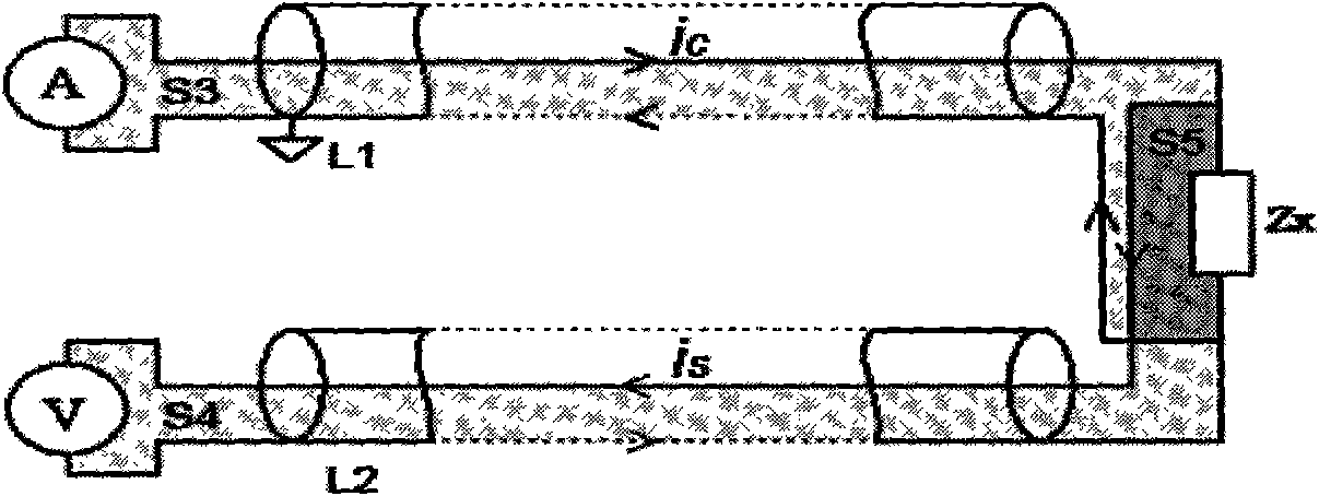
[0022] Such as figure 2 As shown, connect one end of a coaxial cable L1 to the excitation source circuit, and connect the shielding layer of the coaxial cable L1 to the ground wire of the excitation source circuit; connect one end of the other coaxial cable L2 to the sampling circuit phase The shielding layer of the coaxial cable L2 is connected to the input of the negative terminal of the sampling circuit, and its inner core wire is connected to the input of the positive terminal of the sampling circuit; the other ends of the two coaxial cables are respectively connected to the two ends of the Zx under test. This connection method makes the excitation current ic of the excitation circuit (see the arrow for the flow direction) flow through the inner core of the coaxial cable L1, then flow through the device under test Zx, and then flow back to the excitation source through the shielding layer of the coaxial cable L1. The current loop area is the sum of S3 and S5. Since S3 is ...


PUM


Abstract

The invention discloses a two-port testing method of an alternating current milliohm meter, which is used for measuring the resistance and comprises the following steps: firstly, one end of a coaxial-cable is connected with an excitation source circuit, a shielding layer of the coaxial-cable is connected with an earth wire of the excitation source circuit; secondly, one end of the other coaxial-cable is connected with a sampling circuit, a shielding layer of the coaxial-cable is connected with the negative terminal input of the sampling circuit, an inner core wire of the coaxial-cable is connected with the positive terminal input of the sampling circuit; thirdly, the other ends of the two coaxial-cables are respectively connected with two ends of a tested piece; fourthly, excitation current flows through inner cores of the coaxial-cables and then flows through the tested piece, at last flows back to an excitation source through the shielding layers of the coaxial-cables; fifthly, current of the sampling circuit flows through the inner cores of the coaxial-cables, and then flows through the tested piece, at last flows back to the sampling circuit through the shielding layers of the coaxial-cables. The invention reduces the area of the excitation circuit and the sampling circuit, effectively lowers the noise coupling, inhibits the magnetic field coupling interference, obviously improves the interference free performance, and increases the testing accuracy.

Description

technical field [0001] The invention relates to a testing method of an AC milliohm meter, which is used for measuring contact resistance, storage battery internal resistance and supercapacitor equivalent series resistance. Background technique [0002] The test method of the AC milliohm meter is to use a 1kHz AC signal as an excitation signal, apply it to the device under test, and sample its AC voltage value at the same time, and calculate the resistance value according to Ohm's law. Since the measurement resolution of the AC voltage can improve the signal-to-noise ratio by using a band-pass amplifier, a lock-in amplifier, and an integrated integral A / D converter, the final voltage can resolve signals up to 10nV or higher. To measure a resistance of 1μΩ, the excitation current is only 10mA, and the open circuit voltage is easily limited within 20mV, which can fully meet the national standard requirements for contact resistance of electronic components (GB5095 and GBT351 req...

Claims


Application Information

Patent Timeline
Patent Type & Authority Applications(China)
IPC IPC(8): G01R27/02
Inventor 朱正伟何可人
Owner JIANGSU POLYTECHNIC UNIVERSITY
Why Eureka
Try Eureka