Light-splitting prism

A technology for splitting prisms and beams, applied in prisms, optics, optical components, etc., can solve the problems of large influence of splitting polarization and low splitting efficiency, and achieve the effect of wide adaptable wavelength range, high splitting efficiency and easy design.

Inactive Publication Date: 2009-09-23
XI'AN INST OF OPTICS & FINE MECHANICS - CHINESE ACAD OF SCI
View PDF0 Cites 7 Cited by
  • Summary
  • Abstract
  • Description
  • Claims
  • Application Information

AI Technical Summary

Problems solved by technology

[0004] The invention proposes a beam splitting prism, which solves the technical problems of low light splitting efficiency and large influence of light splitting and polarization in the background technology

Method used


Image

  • Light-splitting prism
  • Light-splitting prism

Examples


Embodiment Construction

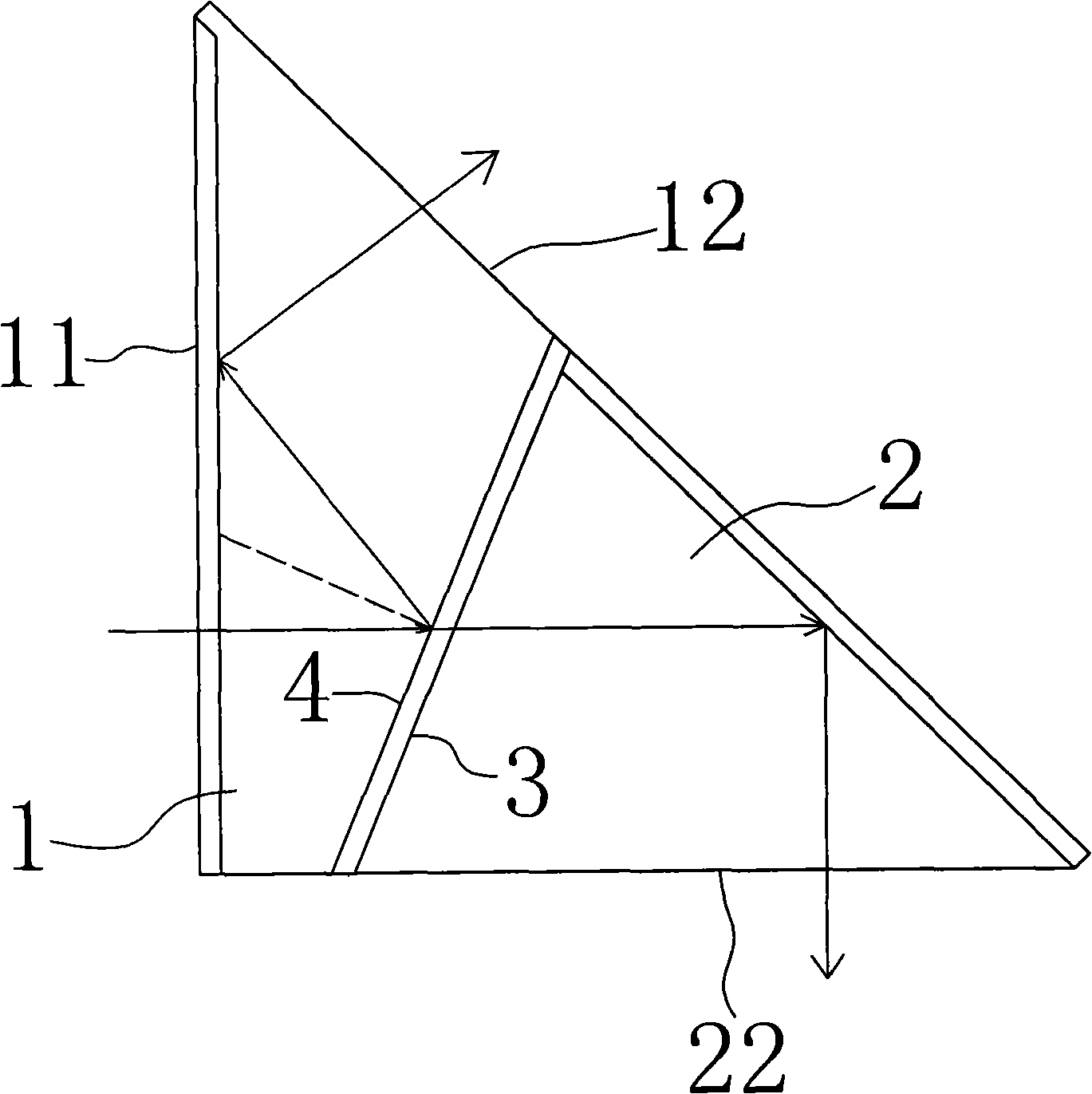
[0026] see figure 1 , a dichroic prism, comprising a first part 1 and a second part 2, the first part 1 and the second part 2 are glued together, the glued surface 3 of the first part 1 and the second part 2 is coated with a beam splitting film 4, and the incident light from The incident surface 11 of the first part 1 is incident, and the glued surface 3 between the first part 1 and the second part 2 is a semi-transparent and semi-reflective beam-splitting surface, and the angle between the incident light and the beam-splitting surface is less than 30 degrees; the incident surface 11 The inner side of the first total reflection surface is the first total reflection surface, and the inner side of the second part 2 along the incident light direction is the second total reflection surface; the light beams reflected by the first total reflection surface and the second total reflection surface are respectively The first exit surface 12 of the first part 1 and the second exit surfac...


PUM


Abstract

The invention provides a light-splitting prism, which comprises a first part (1) and a second part (2), wherein the glued surface (3) of the first part (1) and the second part (2) is placed plated with a beam-splitting film (4); the beam-splitting film (4) is arranged on the first part (1) or the second part (2); incident light is emitted from the incident surface (11) of the first part (1); an included angle between the incident light and the glued surface (3) is less than 30 degrees; the inner side of the incident surface (11) is a first total-reflection surface; the inner side of the second part (2) along the direction of the emitted incident light is a second total-reflection surface; and a light beam reflected by the first total-reflection surface and the second total-reflection surface respectively is transmitted out along the first emergent surface (12) of the first part (1) and the second emergent surface (22) of the second part (2). The prism solves the technical problem that the background art is low in light-splitting efficiency and strong in light-splitting polarization influence, and has the advantages of easy design for the beam-splitting film, wide waveband range of adaptive light, and the like.

Description

technical field [0001] The invention relates to a beam splitting prism, in particular to a dichromatic beam splitting prism used in an astronomical camera. Background technique [0002] Two channels are used in the astronomical camera to detect images from two bands of deep space astronomical targets respectively. Therefore, a dichroic prism is set between the correction lens and the image plane of the camera to divide the visible light to near-infrared 400nm-900nm beam from the astronomical target into two bands of 400nm-650nm and 650nm-900nm. [0003] At present, the more common dichroic prism is a cubic prism, which is made of two 45-degree right-angle prisms glued together and equipped with a beam-splitting film on the 45-degree slope to achieve the purpose of separating visible light and near-infrared bands. . Although this kind of cubic prism only needs one reflection and one transmission to separate the incident light into 90°, the light path in the prism is short, ...

Claims


Application Information

Patent Timeline
IPC IPC(8): G02B27/10G02B5/04
Inventor 陈立武樊学武过晓辉赵葆常马小龙贺应红常凌颖薛彬
Owner XI'AN INST OF OPTICS & FINE MECHANICS - CHINESE ACAD OF SCI
Why Eureka
Try Eureka