Lock device having a multi-part pawl

Technology of a locking device and detent, applied in the field of locking devices

Active Publication Date: 2009-09-23
KIEKERT AG
View PDF0 Cites 22 Cited by
  • Summary
  • Abstract
  • Description
  • Claims
  • Application Information

AI Technical Summary

Problems solved by technology

The "self-opening mechanism" of th

Method used


Image

  • Lock device having a multi-part pawl
  • Lock device having a multi-part pawl
  • Lock device having a multi-part pawl

Examples


Embodiment Construction

[0029] The present invention will be described below with reference to the accompanying drawings and in conjunction with specific embodiments. It must be pointed out that the accompanying drawings particularly show preferred embodiments of the present invention and cannot be used as limitations of the present invention. It is shown diagrammatically below.

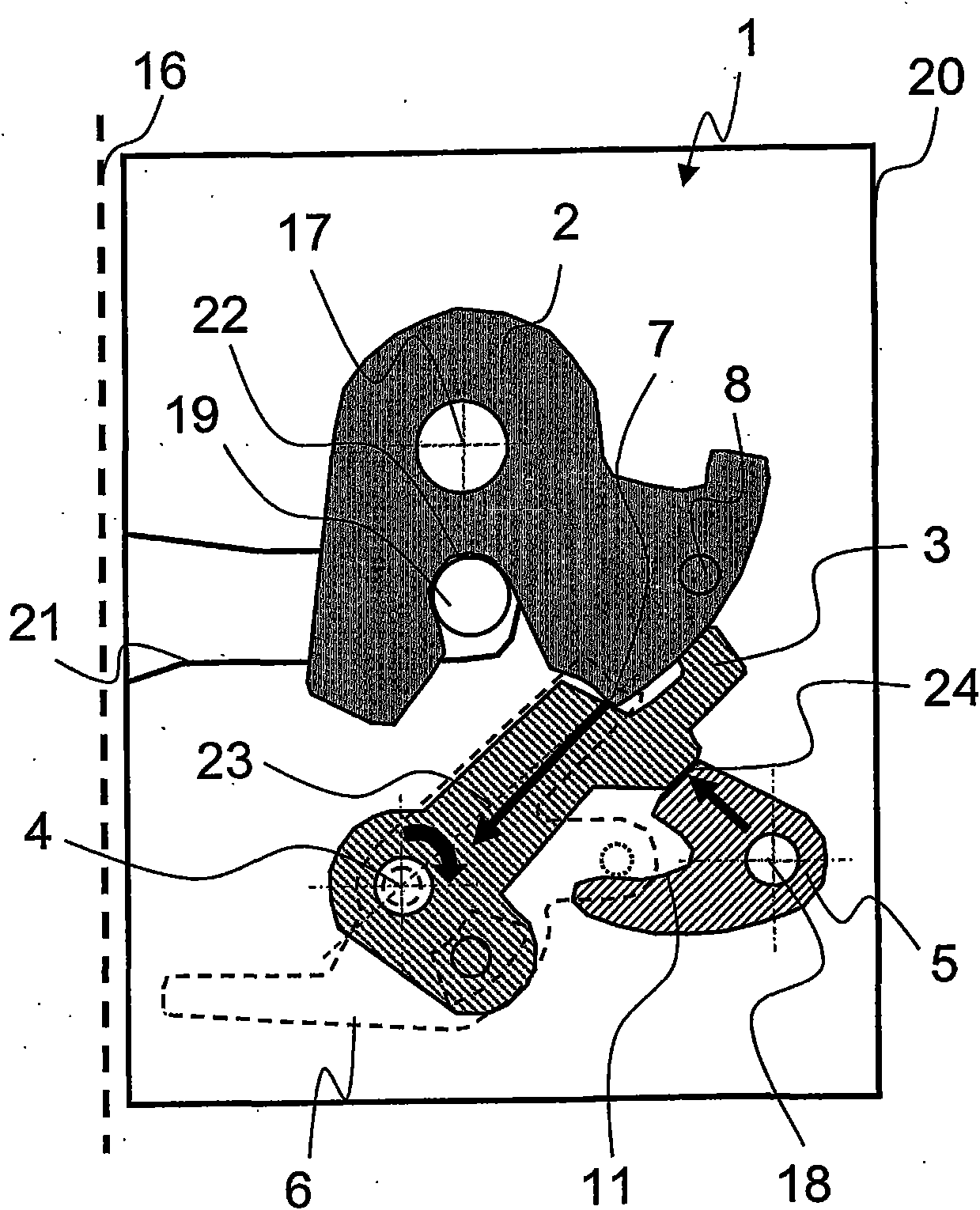
[0030] figure 1A schematic diagram of a locking device 1 of a motor vehicle 16 is shown. The locking mechanism consists of a catch 2 and a first detent 3, and is arranged in a housing 20 such as in or on a car door lock. The locking device 1 is used to fix a clip bolt 19 (also referred to as a striker) to a car body, which is inserted into an inlet 21 when operating during a closing operation of a car door.

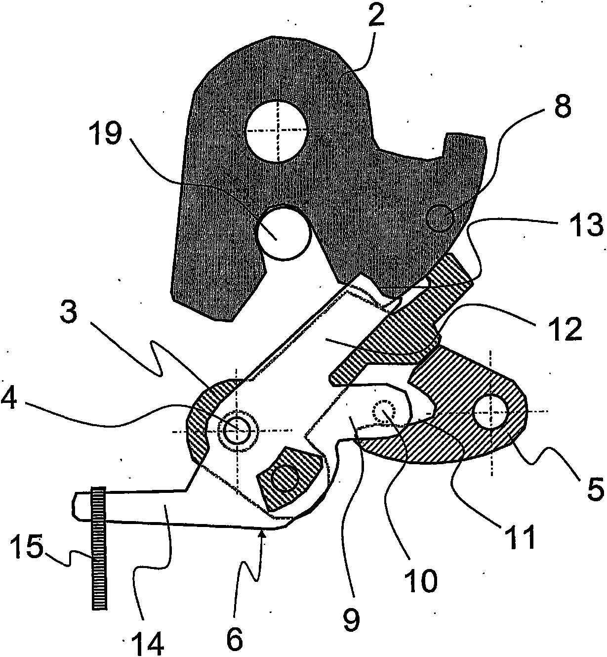
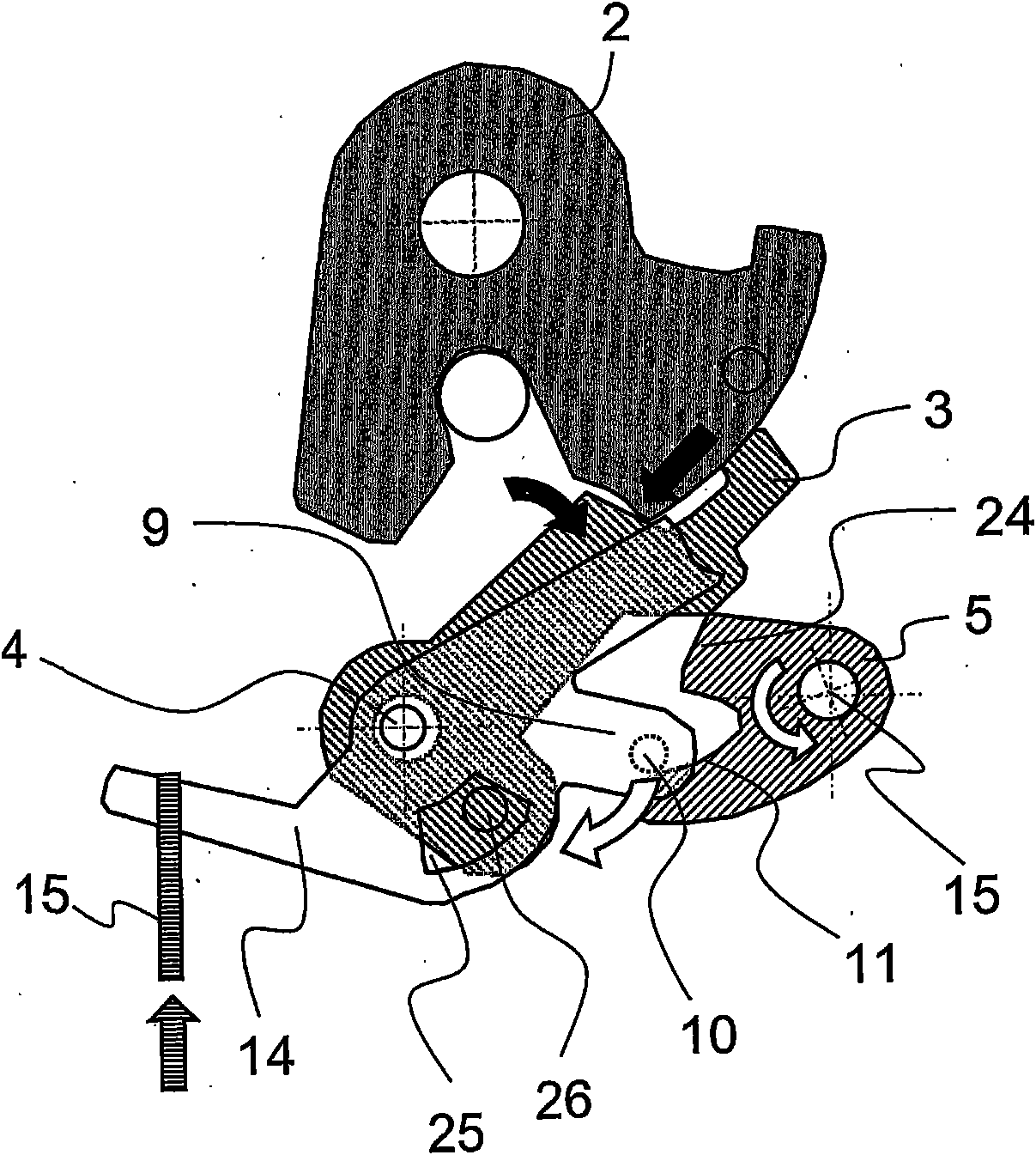
[0031] figure 1 Showing the self-opening mechanism of the locking mechanism, the catch 2 , the first pawl 3 and the locking lever 5 are arranged on one plane of the locking device 1 . In the illustrated locked stat...


PUM


Abstract

The invention relates to a lock device (1) for a motor vehicle, comprising at least one rotary latch (2), a first pawl (3) having a pawl rotational axis (4), and a blocking lever (5), wherein in a locked state of the lock device (1) die rotary latch (2) introduces a pivoting torque into the first pawl (3), and the first pawl (3) is fixed by means of the blocking lever (5), wherein a second pawl (6) is provided, which is supported on the pawl rotational axis (4), and can engage in the blocking lever (5) and the rotary latch (2).

Description

technical field [0001] The invention relates to a locking device comprising: at least one catch, a first catch having a catch rotation axis and an interlocking lever, wherein the catch in the locked state of the locking device transmits a pivoting moment to the first catch, The first pawl is secured by a locking lever. Locking devices of this type are used in particular in automobiles to lock doors, tailgates and the like. Background technique [0002] In the existing locking device, the relative position between the clip and the pawl cannot be designed such that the force exerted by the clip passes through the rotation axis of the pawl to automatically fix the clip through the pawl. On the contrary, in order to provide a locking device capable of working particularly quietly, the pawl in this case is designed or arranged such that the force exerted by the pawl produces a rotational moment on the pawl, thereby effecting the release of the pawl. In this sense, the catch gen...

Claims


Application Information

Patent Timeline
IPC IPC(8): E05B65/32
CPCE05B17/0045E05B85/26E05B2015/1685E05B77/36Y10T292/1047Y10T292/1082Y10T292/1076
Inventor 班德尔托尔斯腾古奥康·瑟康汉尼奇·德克维克赛尔·乌尔里希巴尔特·卡斯滕托普福尔·克劳斯戴施尔·汉斯伊伯特索恩·斯蒂芬林德迈尔·马丁慕赫·沃尔夫冈
Owner KIEKERT AG
Why Eureka
Try Eureka