

A pilot-operated precision overflow valve
An overflow valve and pilot-operated technology, applied in the direction of fluid pressure actuators, servo motor components, mechanical equipment, etc., can solve the problems of restricting wide application, increased overflow pressure, poor flow characteristics, etc., and achieve good flow characteristics , high voltage regulation accuracy, and good voltage regulation characteristics
- Summary
- Abstract
- Description
- Claims
- Application Information
AI Technical Summary
Problems solved by technology
Method used
Image

Examples
Embodiment Construction
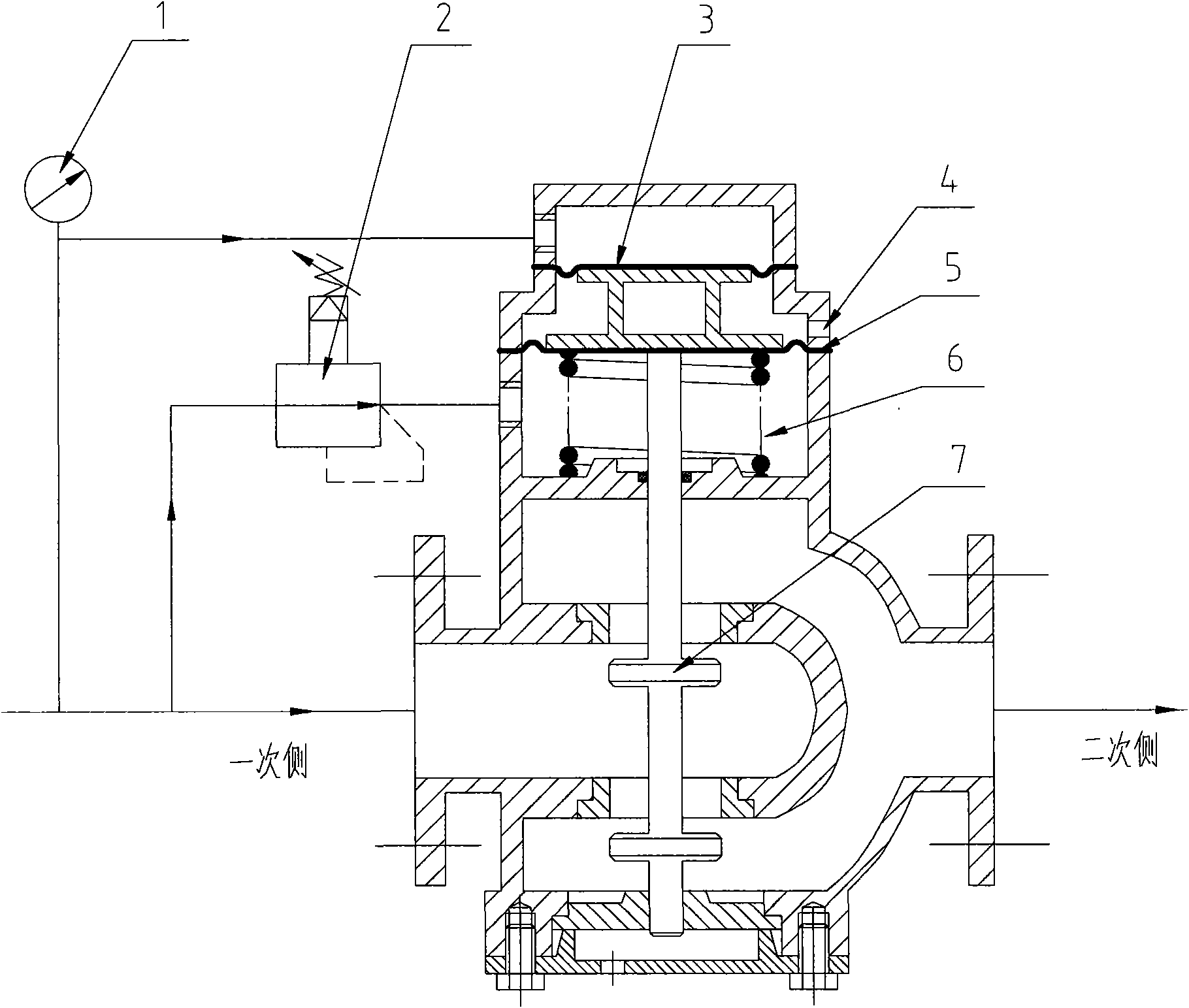
[0013] The present invention will be further described below.
[0014] 1. Setting of overflow pressure
[0015] Under the condition that the upstream pressure of the relief valve is stable, the upstream pressure is p set , the outlet pressure of precision pressure reducing valve (2) is p 2 (pilot pressure), the action area of the upper diaphragm (3) is A 1 , the action area of the lower diaphragm (4) is A 2 . The force produced by spool (7) gravity and soft spring (6) offsets substantially, and its size can be ignored.
[0016] From the force balance equation of the double-layer diaphragm structure:
[0017] p set A 1 =p 2 A 2
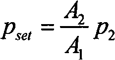
[0018] have to: p set = A 2 A 1 p 2
[0019] p set That is, the set value of the overflow pressure, which is determined by p 2 Sure. Set p by adjusting t...
PUM
 Abstract
Description
Claims
Application Information