Double-diaphragm pressure stabilizer

A technology of voltage stabilizer and diaphragm, applied in the direction of safety valve, engine element, balance valve, etc., can solve the problems of voltage stabilizer failure, valve stem jam, increase unbalanced force of valve core, etc., to achieve stable voltage High precision, sensitive action and good stability

Pending Publication Date: 2020-11-27
江苏盛伟燃气科技有限公司
View PDF0 Cites 3 Cited by
  • Summary
  • Abstract
  • Description
  • Claims
  • Application Information

AI Technical Summary

Problems solved by technology

This structure has the following problems in practical application: 1. The inner hole of the valve port h acts as a guide hole. Because of the small matching gap with the valve stem i, the impurities in the gas are easy to cause blockage and make the valve stem i produces jamming phenomenon; 2. The gas will generate a large amount of cold energy in the process of pressure regulation, thermal expansion and contraction can easily make the valve stem i and valve port h locked, and because the gas contains moisture, the existence of cold energy often makes the The valve stem i and the valve port h freeze together, resulting in ice blockage; 3. Because the valve stem i occupies the cross-sectional area of ​​the inner hole of the valve port h, the actual cross-sectional area of ​​the inner hole of the valve port h is much larger than the flow area, increasing Increased spool (flap) unbalanced force
These problems affect the stability and reliability of the voltage regulator, and even cause the voltage regulator to fail

Method used


Image

  • Double-diaphragm pressure stabilizer
  • Double-diaphragm pressure stabilizer
  • Double-diaphragm pressure stabilizer

Examples


Embodiment Construction

[0022] First of all, it needs to be explained that the orientation words such as up, down, left, right, front, and back described in the present invention are only described according to the accompanying drawings, so as to be easy to understand, and are not intended to limit the technical solution and scope of protection of the present invention. .

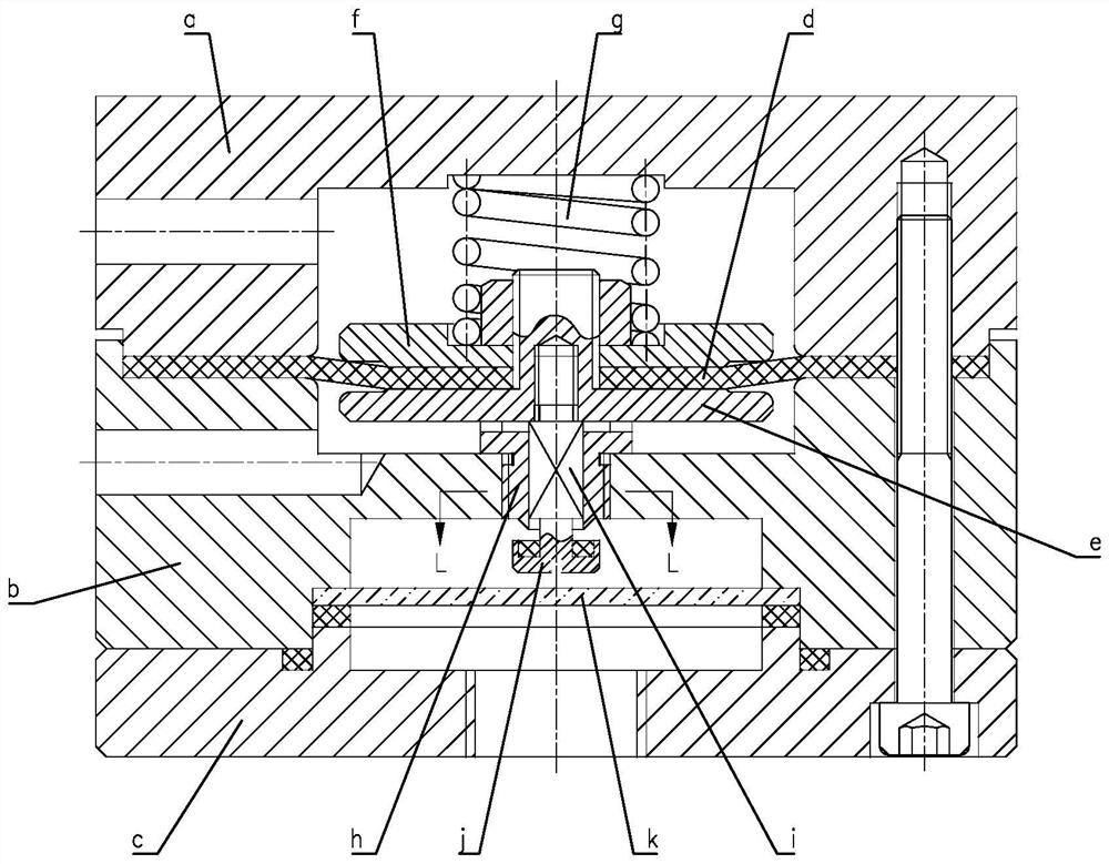
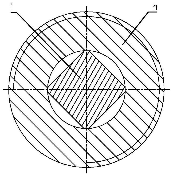
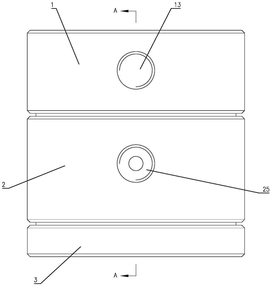
[0023] Such as Figure 3 to Figure 7 Shown is a specific embodiment of a double-diaphragm regulator of the present invention, including an upper cover 1 , a valve body 2 and a lower cover 3 arranged in sequence from top to bottom. The upper cover 1 is provided with a first groove 11 and a first receiving groove 12 from bottom to top, and a first air inlet 13 communicating with the first receiving groove 12 is arranged on the left side of the upper cover 1 . The valve body 2 is provided with a second groove 21 and a third groove 22 correspondingly on the upper and lower sides. A valve port 24 is provided, a second air inlet 25 co...


PUM


Abstract

The invention relates to a double-diaphragm pressure stabilizer. The double-diaphragm pressure stabilizer comprises an upper cover, a valve body and a lower cover. The upper cover is provided with a first groove, a first accommodating groove and a first air inlet hole. The valve body is provided with a second groove, a third groove, a channel, a valve port, a second air inlet and an air outlet. The lower cover is provided with a fourth groove. The double-diaphragm pressure stabilizer further comprises an upper diaphragm, a lower diaphragm and a pressure stabilizing spring. The periphery of theupper diaphragm is pressed between the upper cover and the valve body. A first upper disc and a first lower disc are correspondingly arranged on the upper side and the lower side of the upper diaphragm. The periphery of the lower diaphragm is squeezed between the valve body and the lower cover. A second upper disc and a second lower disc are correspondingly arranged on the upper side and the lower side of the lower diaphragm. A rubber valve pad right opposite to the valve port is arranged on the upper lateral side of the second upper disc. The second upper disc is fixedly connected with the first lower disc through a connecting piece. The pressure stabilizing spring is located in the first accommodating groove, and the lower end of the pressure stabilizing spring is pressed on the first upper disc. The double-diaphragm pressure stabilizer has the advantages of being simple in structure, sensitive in action, safe, reliable, good in stability and high in pressure stabilization precision.

Description

technical field [0001] The invention relates to a gas pressure regulator, in particular to a double-diaphragm voltage regulator used for the pilot of the gas pressure regulator. Background technique [0002] In the field of gas transmission and distribution, as an important valve in the gas pipeline network, the pressure regulator plays the role of regulating and stabilizing the pressure. Gas pressure regulators are divided into direct-acting regulators and indirect-acting regulators. Indirect-acting regulators use outlet pressure changes and are amplified by the pilot to control the driver to drive the movement of the regulating element. As an important part of the pilot of the gas pressure regulator, the voltage stabilizer mainly plays the following roles: reduce the unbalanced force of the spool of the pilot; improve the resolution of the pilot; reduce the withstand pressure difference of the main valve diaphragm of the pressure regulator . These functions can effective...

Claims


Application Information

Patent Timeline
Patent Type & Authority Applications(China)
IPC IPC(8): F16K17/30
CPCF16K17/30
Inventor 陈伟忠于翠翠赵学朋姜大春李海蔡建
Owner 江苏盛伟燃气科技有限公司
Why Eureka
Try Eureka