Supercharge Your Innovation With Domain-Expert AI Agents!

Stop element system and stop element for concrete formwork

A technology of concrete formwork and stopper, which is applied to the connection of formwork/formwork/work frame, the on-site preparation of building components, and construction, etc., can solve problems such as high cost and achieve the effect of reducing the number of parts

Inactive Publication Date: 2009-10-21
HILTI AG
View PDF1 Cites 0 Cited by
  • Summary
  • Abstract
  • Description
  • Claims
  • Application Information

AI Technical Summary

Problems solved by technology

[0003] The disadvantage here is that, when placing formwork for concrete walls or ceilings of defined wall thickness, each pair of such stop bodies must be mounted at a defined distance from each other, so that the formwork walls are at a defined distance from each other, which distance equivalent to desired concrete wall or ceiling wall thickness
The consequence: the distance of the stop body always has to be measured in the thickness direction of the formwork, which means high costs on the construction site

Method used


Image

  • Stop element system and stop element for concrete formwork
  • Stop element system and stop element for concrete formwork
  • Stop element system and stop element for concrete formwork

Examples


Embodiment Construction

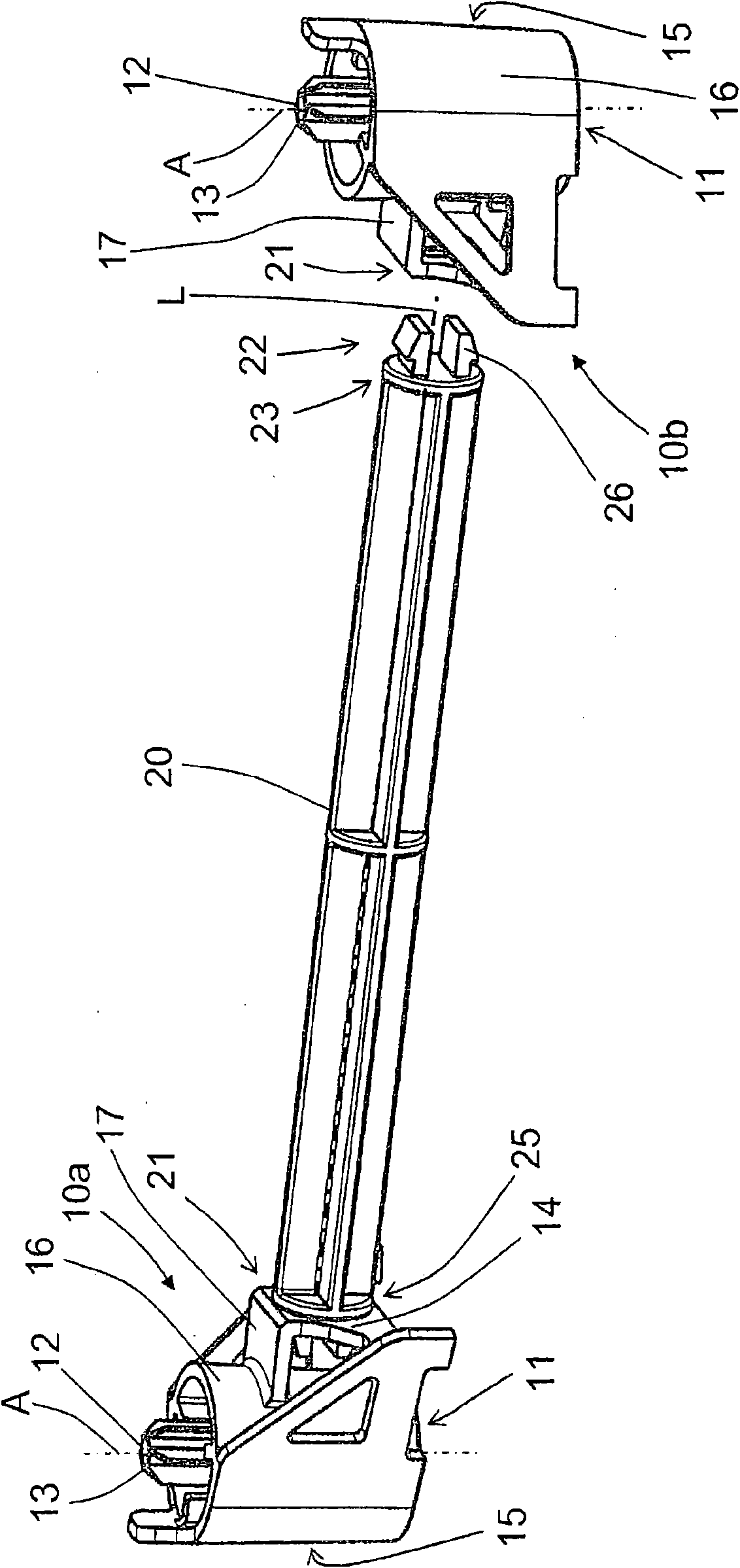
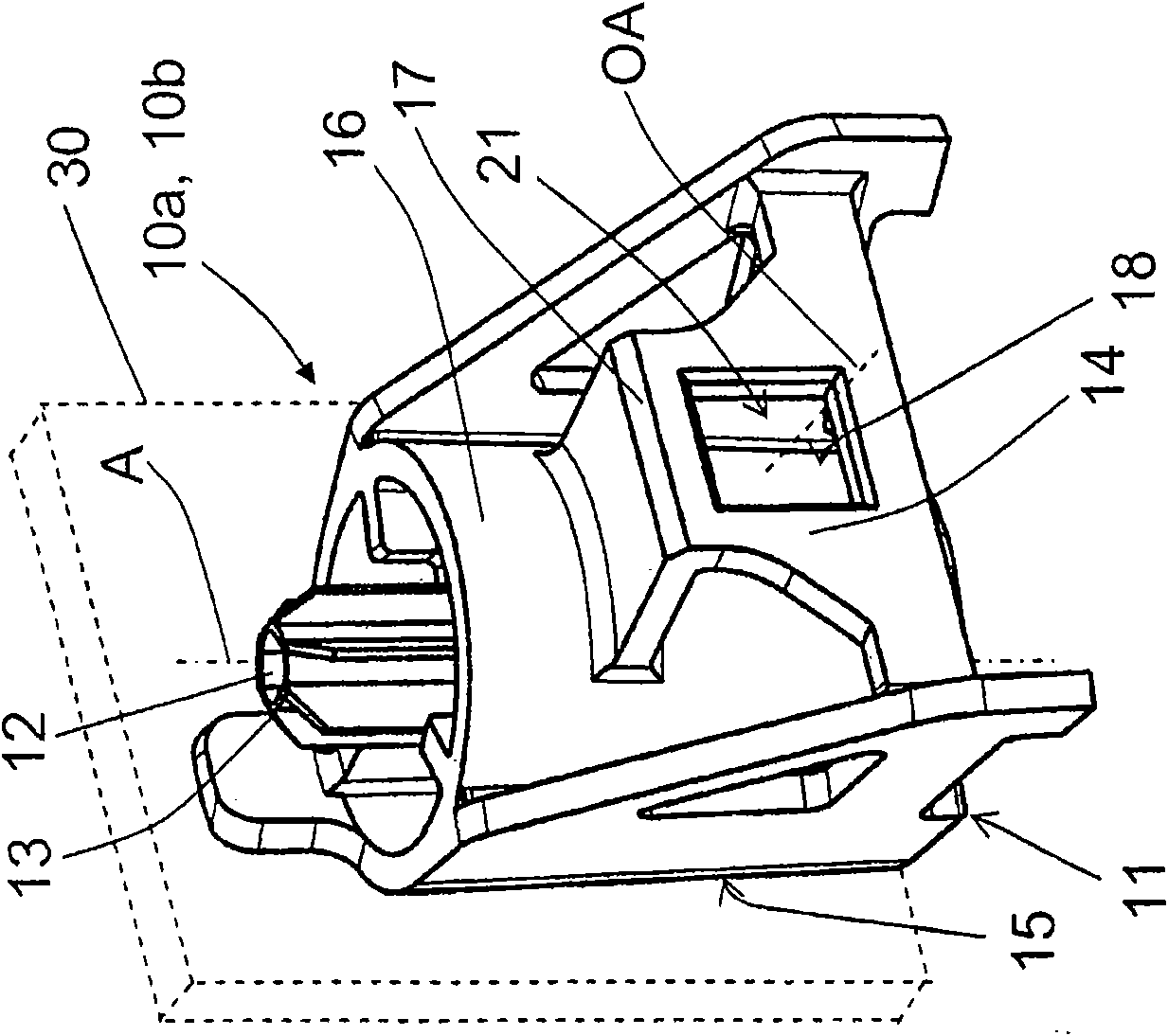
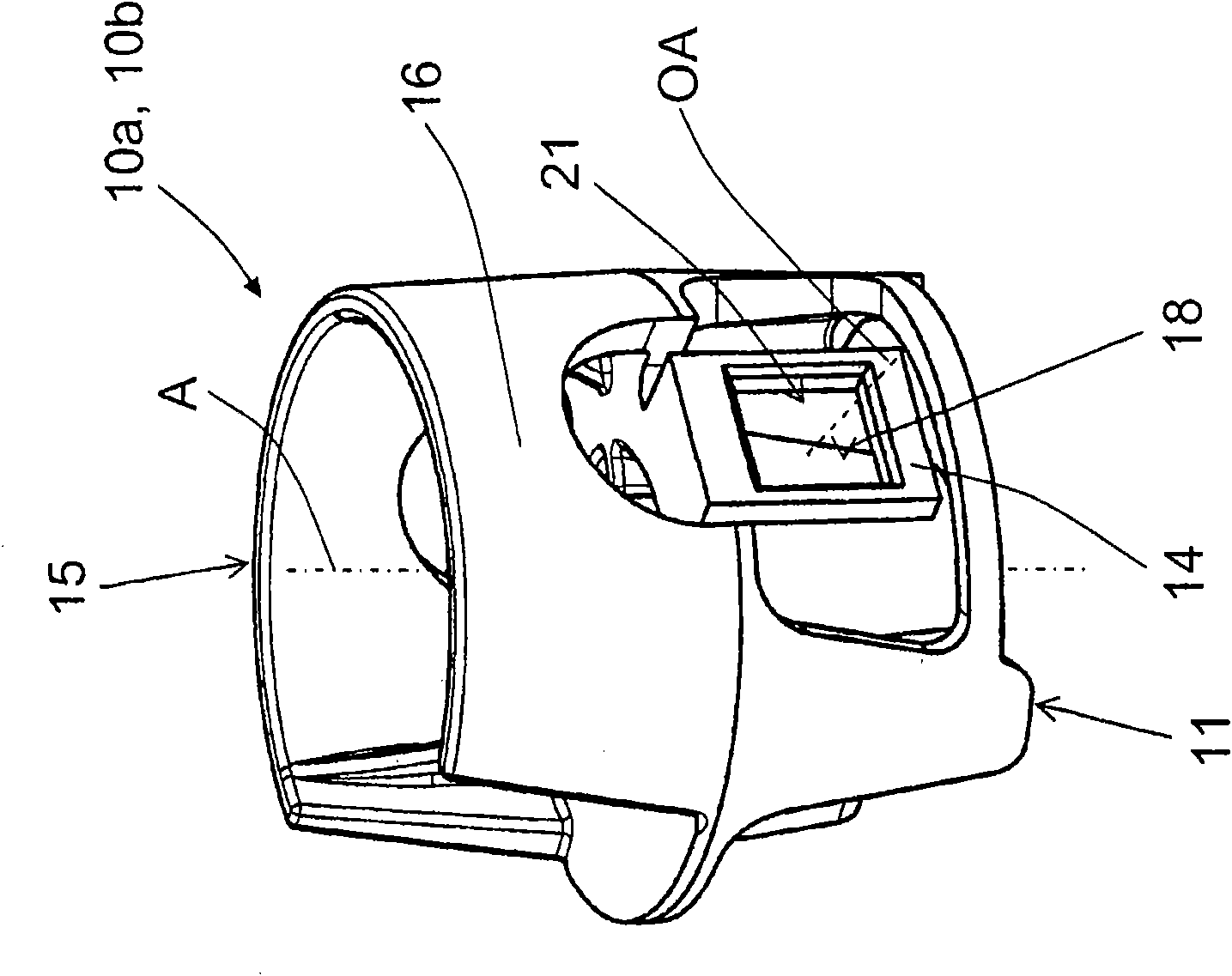
[0024] exist figure 1 with 2a shows the stop body system according to the invention. exist figure 1 2 shows two stop bodies 10 a , 10 b of the stop body system and a spacer element 20 , wherein the first stop body 10 a is fixedly connected to the spacer element 20 via a coupling device to be described in detail. The stop bodies 10a, 10b have a base 11 for mounting on a structural component and a through-hole 12 defining the fixed axis A. As shown in FIG. Around the through hole 12 is formed a seat 13 for the fixing element. In addition, the stop body 10a, 10b also has a peripheral wall 16 and at least one stop surface 15 for the formwork arm 30 (see Figure 2a ), wherein the stop surface 15 can be at least partially formed by the peripheral wall 16 . On the brackets 17 projecting laterally from the peripheral walls 16 of the stop bodies 10a, 10b respectively, a bayonet opening 18 constituting the engagement mechanism 21 is arranged in a wall section 14, wherein the openin...


PUM


Abstract

The invention relates to stop element system and stop element for concrete formwork, wherein the stop element system has stop element (10) with each having a base (11) for being placed on a constructional component, a through-opening (12) with a support (13) for defining an attachment axis (A) and fixing the elements, and at least one stop element surface for concrete wall (30). At least the two stop elements (10a, 10b) can connect with each other through at least one elongate spacer (20, 20a, 20b) at a predetermined distance.

Description

technical field [0001] The invention relates to a stop body system for the lateral support of concrete formworks of the type mentioned in the preamble of claim 1 and to a stop body of the type mentioned in the preamble of the co-dependent claims. Background technique [0002] From EP 0 971 084 A1 a stop body for concrete formwork is known, which has a base for mounting the stop body on a structural part, a through-hole for a pin and a support . The stop body can be fastened to the structural part by means of pins. Furthermore, the stop body has a stop surface for the formwork wall. [0003] The disadvantage here is that, when placing formwork for concrete walls or ceilings of defined wall thickness, each pair of such stop bodies must be mounted at a defined distance from each other, so that the formwork walls are at a defined distance from each other, which The distance corresponds to the desired concrete wall or ceiling wall thickness. The result is that the distance of...

Claims


Application Information

Patent Timeline
Patent Type & Authority Applications(China)
IPC IPC(8): E04G17/06
CPCE04G17/0758E04G17/064
Inventor T·福塞尔F·洛尔
Owner HILTI AG
Features
  • R&D
  • Intellectual Property
  • Life Sciences
  • Materials
  • Tech Scout
  • Unparalleled Data Quality
  • Higher Quality Content
  • 60% Fewer Hallucinations
Learn More