Reflection optical filter

A filter, reflective technology, applied in the field of filters, can solve the problems of reducing image color saturation, color saturation decline, poor spectral resolution, etc., to improve the efficiency of use and enhance the effect of color saturation

Inactive Publication Date: 2009-10-21
WINTEK CORP
View PDF1 Cites 17 Cited by
  • Summary
  • Abstract
  • Description
  • Claims
  • Application Information

AI Technical Summary

Problems solved by technology

[0005] Taking the red pigment resin pattern 140 as an example, the way to filter the light source is to partially absorb the green light and the blue light, and only let the red light pass through. In this way, after the light source passes through the color filter 100, only about 3 brightness, resulting in poor light utilization efficiency. In addition, the red, green and blue spectral resolutions filtered out by the red, green and blue pigment resin patterns 140, 150 and 160 are not ideal. Reduce color saturation when displaying images
[0006] In addition, as for the reflective color filter disclosed in No. WO9517690 patent document, it only uses the principle of Fabry-Perot optical cavity interference (optics scavity interference) to filter light. Wide, so that the colors presented are not narrow-band red, green and blue colors, so there is still a problem of poor spectral resolution, resulting in a decrease in color saturation

Method used


Image

  • Reflection optical filter
  • Reflection optical filter
  • Reflection optical filter

Examples


Embodiment Construction

[0031] The above and other technical features and advantages of the present invention will be described in more detail below in conjunction with the accompanying drawings.

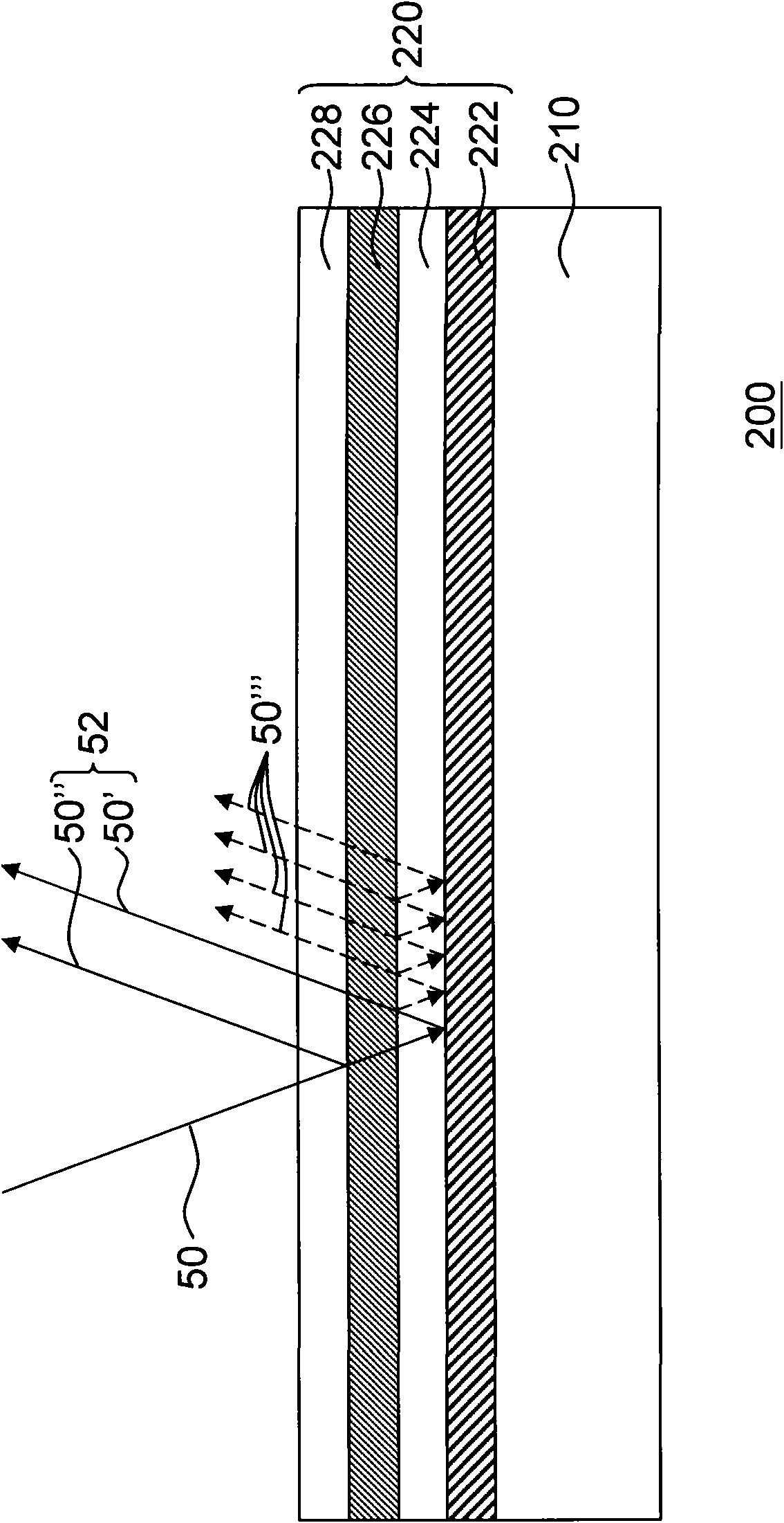
[0032] figure 2 It is a schematic diagram of a reflective filter according to an embodiment of the present invention. Please refer to figure 2 The reflective filter 200 of the present invention includes a substrate 210 and an optical film structure 220 disposed on the substrate 210. The optical film structure 220 stacks a reflective film 222, a gap film 224, and a semi-permeable film 226 in sequence. And a transparent optical film 228, that is, the reflective film 222 is located on the surface of the substrate 210, and the gap film 224 is located on the surface of the reflective film 222, and the semi-permeable film 226 is located on the surface of the gap film 224, and the transparent optical film 228 is located on the semi-permeable film 226 surface.

[0033] When the incident light 50 enters the re...


PUM

PropertyMeasurementUnit
refractive indexaaaaaaaaaa
reflectanceaaaaaaaaaa

Abstract

The invention is a reflection optical filter comprising a substrate and an optical film-layer structure arranged on the surface of the substrate. The optical film-layer structure comprises a reflection film, an interstitial film, a semi-transparent film and a transparent optical film; the reflection optical filter can filter the colorful light in the narrow band spectrum through the reflection and the interference among each layer of the optical film-layer structure so as to improve the color saturation of images.

Description

technical field [0001] The invention relates to an optical filter, and in particular to a reflective optical filter. Background technique [0002] With the advancement of modern video technology, liquid crystal display devices have been widely used on the display screens of consumer electronic products such as mobile phones, watches and personal digital assistants (PDAs). Under the trend of low power consumption research and development, reflective ) or transflective liquid crystal display devices have developed quite rapidly recently. [0003] Generally speaking, a reflective or transflective liquid crystal display device is configured with a color filter to achieve a color image display effect during reflective display. [0004] figure 1 It is a schematic diagram of an existing color filter. Please refer to figure 1 , the existing color filter 100 includes a substrate 110, a reflective film 120, a black matrix (black matrix) 130 and a plurality of red pigment resin pat...

Claims


Application Information

Patent Timeline
Patent Type & Authority Applications(China)
IPC IPC(8): G02B5/28B32B33/00G02F1/1335
Inventor 王文俊黄敬佩刘锦璋陈逸书陈冠霖
Owner WINTEK CORP
Why Eureka
Try Eureka