Magnetic control gear shifting hub

A technology of shifting wheels and hubs, which is applied in the field of wheel power transmission devices and magnetically controlled shifting hubs, can solve the problems of insufficient power, stuck reverse carts, and small size.

Pending Publication Date: 2021-05-11
李绵军
View PDF1 Cites 0 Cited by
  • Summary
  • Abstract
  • Description
  • Claims
  • Application Information

AI Technical Summary

Problems solved by technology

[0002] Most of the current electric vehicles use the direct drive mode of hub motors, especially electric two-wheeled vehicles, which have the disadvantages of small size, limited battery compartment space, and limited battery capacity, so the size and power of the motor cannot be made larger
If an electric vehicle wants to drive on complex terrain such as mountains and hills, it needs more power and consumes more power. However, the reality is that the required power cannot be met, making it difficult for electric vehicles to drive on complex terrain such as mountains and hills. , thus limiting the scope of use of electric vehicles
In addition, although a speed changer is arranged in the hub motor at present, its high-speed direct drive block directly drives the wheels by the electromagnetic clutch, and additionally increases a large electric energy loss (the power consumption loss of the electromagnetic clutch work) at the same time. The space of the wheel hub motor is limited, the size and power of the electromagnetic clutch cannot be enlarged, and the electromagnetic suction generated by it is not enough to tighten the friction plate to drive the outer wheel hub to directly drive the wheel to drive with a load. If the clutch is used forcibly, it will cause the clutch to slip and fail, and the slip time is too long. Clutch friction The heat transferred to the motor makes the motor winding easy to burn the motor when the high temperature increases sharply. Due to the slipping of the clutch, if the vehicle suddenly has no power output when dri

Method used


Image

  • Magnetic control gear shifting hub
  • Magnetic control gear shifting hub
  • Magnetic control gear shifting hub

Examples


Embodiment 1

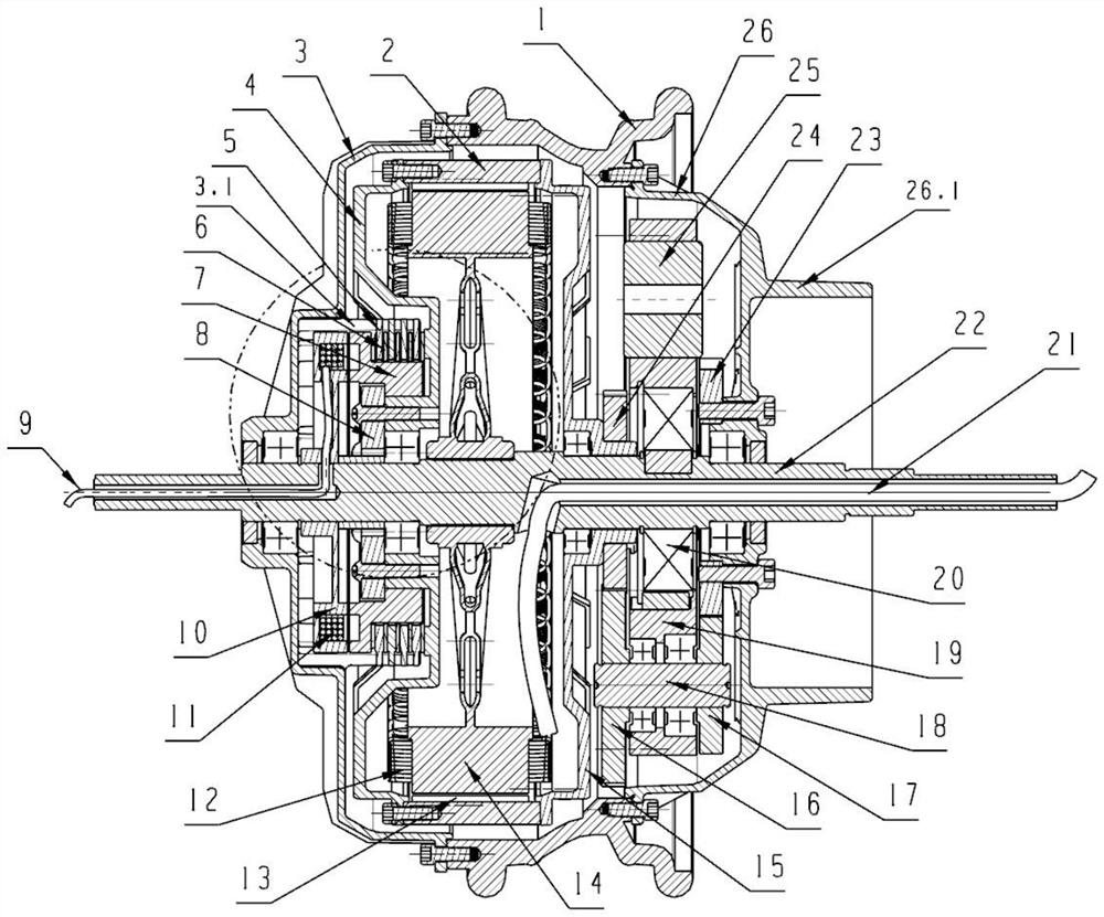
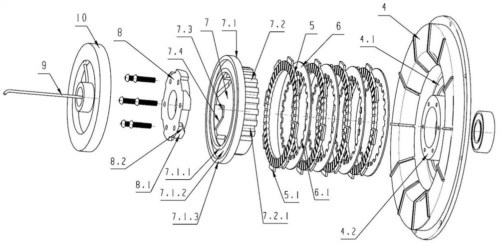
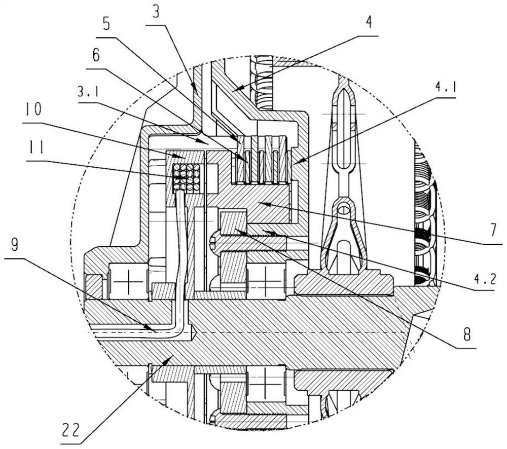
[0040] see Figure 1 to Figure 12, a magnetically controlled shifting hub, comprising a motor spindle 22 and a hub steel ring 1, the two ends of the hub steel ring 1 are respectively installed with a hub left cover 3 and a hub right cover 26, and a motor is provided on the motor spindle 22, and the motor includes a rotor 2 And the stator 14, the motor winding 12 is laid on the stator 14, the magnetic steel sheet 13 is provided between the rotor 2 and the stator 14, the motor two ends are respectively the motor left cover 4 and the motor right cover 15, the motor left cover 4 and the motor right cover 15 is fixedly connected with the rotor 2, the motor wire 21 is led out from the shaft hole at the right end of the motor main shaft 22, the gearbox body is formed in the hub cavity, the clutch and the gear set are arranged in the gearbox body, and the shaft hole end of the motor left cover 4 is provided with a boss 4.2, the clutch is set on the boss 4.2 with the driven hub 7 and t...

Embodiment 2

[0053] see Figure 13 to Figure 20 , the similarity between it and Embodiment 1 will not be repeated here, the difference lies in the position of the motor clutch.

[0054] It is fixedly connected with the first suction disk 27 on the side of the pressure plate on the driven hub 7, the other side of the first suction disk 27 is provided with the fifth magnetic conduction ring 27.1, and the coil ring groove 10.3 of the electric suction disk 10 is set inside. The ring frame 28, the coil 11 is wound on the ring frame 28, the fifth magnetically conductive ring 27.1 is nested in the shaft hole at one end of the ring frame 28, and the shaft hole at the other end of the ring frame 28 contacts the fourth magnetically conductive ring of the electric chuck 10 10.4, there is a certain gap between the fourth magnetic conduction ring 10.4 and the fifth magnetic conduction ring 27.1, the fifth magnetic conduction ring 27.1 is attracted by the fourth magnetic conduction ring 10.4 after the e...

Embodiment 3

[0060] see Figure 21 ~ Figure 23 , the similarities between it and Embodiment 1 and Embodiment 2 will not be repeated here, the difference lies in the electromagnetic shifting position. Specifically, the second suction disc 29 and the support disc 30 are installed in the hub cavity where the hub left cover 3 is located on the motor main shaft 22, the second suction disc 29 is connected with the first suction disc 27 through a bearing, and the second suction disc 29 is connected with the first suction disc 27 through a bearing. The disk 29 can slide horizontally on the motor shaft 22. The center of the support disk 30 has a shaft hole 30.1. Several electric suckers 10 are installed on the support disk 30. The ring skeleton 28 is set in the electric sucker 10, and the coil 11 is wound on the ring skeleton 28. One end of the shaft hole of the ring frame 28 is installed with a fixed iron core 10.5, and a plurality of moving iron cores 29.1 are installed on the second suction plat...


PUM


Abstract

The invention discloses a magnetic control gear shifting hub, and belongs to the technical field of wheel power transmission. The gearbox comprises a motor spindle and a hub steel ring, a gearbox body is formed in a hub cavity, and a clutch and a gear set are arranged in the gearbox body. An electric suction cup is installed on a motor spindle, a magnetic conductive ring and a coil annular groove are arranged on the side wall of the side, adjacent to the pressing disc, of the electric suction cup, and a coil is arranged in the coil annular groove; and a concave cavity is formed in the portion, close to the protruding column, of the motor left cover. The driven friction plate and the driving friction plate are located on the protruding disc and located in the concave cavity. The clutch gear shifting mechanism is installed on the motor in the hub, wherein the electric suction cup is arranged outside the motor shell, the motor is an independent part and does not interfere with each other; therefore, heat generated when the electric suction cup is powered on to work cannot be overlapped in the motor at the same time, a motor heating source is not additionally added, so that the motor is protected, and the electric suction cup is prevented from being burnt out due to overtemperature caused by superposition of heat generated by working of the motor.

Description

technical field [0001] A magnetically controlled shifting wheel hub belongs to the technical field of wheel power transmission, in particular to wheel power transmission devices of electric motorcycles and electric bicycles. Background technique [0002] Most of the current electric vehicles are directly driven by hub motors, especially electric two-wheeled vehicles, which have the disadvantages of small size, limited battery compartment space, and limited battery capacity, so the size and power of the motor cannot be made larger. If an electric vehicle wants to drive on complex terrain such as mountains and hills, it needs more power and consumes more power. However, the reality is that the required power cannot be met, making it difficult for electric vehicles to drive on complex terrain such as mountains and hills. , thereby limiting the scope of use of electric vehicles. In addition, although a speed changer is arranged in the hub motor at present, its high-speed direct...

Claims


Application Information

Patent Timeline
IPC IPC(8): B62M7/12B62M25/08H02K7/116H02K7/108
CPCB62M7/12B62M25/08H02K7/108H02K7/116
Inventor 李绵军袁长安唐宏李洪兵康辉谢明江刘军
Owner 李绵军
Why Eureka
Try Eureka