Millimeter wave 16-channel transmit-receive frequency conversion channel assembly

A millimeter wave, channel technology, applied in electrical components, multi-frequency modulation and transformation, transmission systems, etc., can solve the problems of complex circuit assembly, low space utilization, large volume, etc., to improve reliability and stability, and environmental adaptation. Strong ability, small size effect

Active Publication Date: 2017-04-26
CHENGDU RDW TECH CO LTD
View PDF6 Cites 20 Cited by
  • Summary
  • Abstract
  • Description
  • Claims
  • Application Information

AI Technical Summary

Problems solved by technology

[0004] 1. The traditional frequency conversion channel is divided into three independent modules: receiving, transmitting, and local oscillator. Each module has a single function, low integration, large system volume, and complicated circuit assembly;
[0005] 2. The traditional frequency conversion channel has many types and quantities of devices, and various assembly methods, which pose great challenges to reliability and stability in complex use environments;
[0006] 3. The traditional frequency conversion channel adopts a single-sided wiring design on a soft substrate. The layout and wiring of components are usually arranged in a straight line, and the space utilization rate is low;
[0007] 4. The traditional frequency conversion channel usually uses waveguide filters, cavity filters and other devices with large volume, heavy weight, and poor temperature stability, which cannot meet the special installation and use of missile-mounted, airborne, and backpack-type. surroundings

Method used


Image

  • Millimeter wave 16-channel transmit-receive frequency conversion channel assembly
  • Millimeter wave 16-channel transmit-receive frequency conversion channel assembly
  • Millimeter wave 16-channel transmit-receive frequency conversion channel assembly

Examples


Embodiment 1

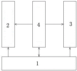
[0031] A millimeter-wave 16-channel transceiver frequency conversion channel assembly has a three-layer structure as a whole, the upper layer includes a power control part 1, the middle layer is a frequency conversion circuit part, and the lower layer includes 16 waveguide interfaces; the frequency conversion circuit part includes 16 receiving channels 2, 1 Transmitting channel 3 and local oscillator processing circuit 4, receiving channel 2 and transmitting channel 3 share 16 waveguide interfaces, send and receive time-sharing power supply, switch channels through radio frequency switches, and exchange power and control signals between layers through miniature low-frequency connectors The radio frequency signals are interconnected through radio frequency insulators; each layer is interconnected through via holes. The stacked structure design is designed in layers and partitions according to the signal operating frequency, different signal types, and different circuit functions...

Embodiment 2

[0033]A millimeter-wave 16-channel transceiver frequency conversion channel assembly, characterized in that: the overall structure is a three-layer structure, the upper layer includes a power control part 1, the middle layer is a frequency conversion circuit part, and the lower layer includes 16 waveguide interfaces; the frequency conversion circuit part includes 16 channels Receive channel 2, 1 transmit channel 3 and local oscillator processing circuit 4, receive channel 2 and transmit channel 3 share 16 waveguide interfaces, send and receive time-sharing power supply, switch channels through radio frequency switches, power and control signals between layers pass through Miniature low-frequency connectors are interconnected, and radio frequency signals are interconnected through radio frequency insulators; each layer is interconnected through via holes.

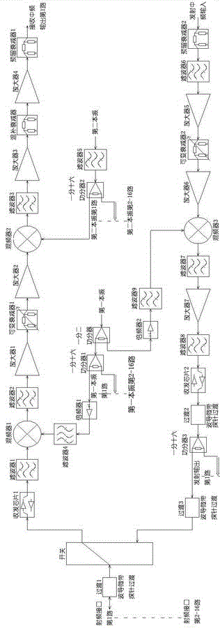
[0034] The 16 receiving channels 2 undergo frequency conversion twice to realize the conversion between the millimeter-wave...


PUM


Abstract

The invention relates to the technical field of a transmit-receive frequency conversion channel, and discloses a millimeter wave 16-channel transmit-receive frequency conversion channel assembly, which mainly adopts a mixed design of an MMIC bare chip and an LTCC circuit and realizes a microminiature design through one or more frequency conversion. The transmit-receive frequency conversion channel assembly is in a three-layer structure on the whole, wherein the upper layer comprises a power control portion, the middle layer is a frequency conversion circuit portion and the lower layer comprises 16 paths of waveguide interfaces. The frequency conversion circuit portion comprises 16 paths of receiving channels, one path of emission channel and a local oscillator processing circuit. The receiving channels and the emission channel share the 16 paths of waveguide interfaces; transmit-receive time-sharing power supply is realized; channel switching is carried out through a radio frequency switch; power supply and control signals between the layers are connected through a miniature low-frequency connector; radio frequency signals are connected through a radio frequency isolator; and the layers are internally connected through via holes. Therefore, the millimeter wave 16-channel transmit-receive frequency conversion channel assembly realizes high-density integration of millimeter wave multi-channel transmit-receive frequency conversion channels, is small in size, light in weight and high in environment adaption capability, improves working stability and reliability of the system in various environment conditions, and meets the future trend of transmit-receive frequency conversion channel miniaturization.

Description

technical field [0001] The invention relates to the technical field of transceiver frequency conversion channels, and is a millimeter-wave 16-channel transceiver frequency conversion channel component mainly adopting a mixed design of MMIC bare chips and LTCC circuits, and realizing miniaturization design through one or multiple frequency conversion methods. Background technique [0002] The frequency conversion channel is a bridge connecting the radio frequency part and the baseband part, and is a key part of modern radio communication and radio detection. In modern information warfare, frequency conversion channels play an important role. The size of a radio, such as an antenna, is directly proportional to the radio wavelengths it receives and transmits. The low-frequency signal carrying information needs to be converted once or more times to move the spectrum to the radio frequency part, so that it can be transmitted with an antenna of suitable size; the radio wave recei...

Claims


Application Information

Patent Timeline
Patent Type & Authority Applications(China)
IPC IPC(8): H04B1/00H03D7/16
CPCH03D7/16H04B1/0057
Inventor 章圣长吴仕强
Owner CHENGDU RDW TECH CO LTD
Why Eureka
Try Eureka