

Magnet retaining relay
A magnetic latching relay and magnetic circuit technology, applied in the direction of electromagnetic relays, relays, detailed information of electromagnetic relays, etc., can solve the problems of high assembly difficulty, high precision of parts size, high precision, etc., and achieve reduced manufacturing difficulty, balance of suction and reaction force, The effect of improving stability
- Summary
- Abstract
- Description
- Claims
- Application Information
AI Technical Summary
Problems solved by technology
Method used
Image

Examples
Embodiment 1
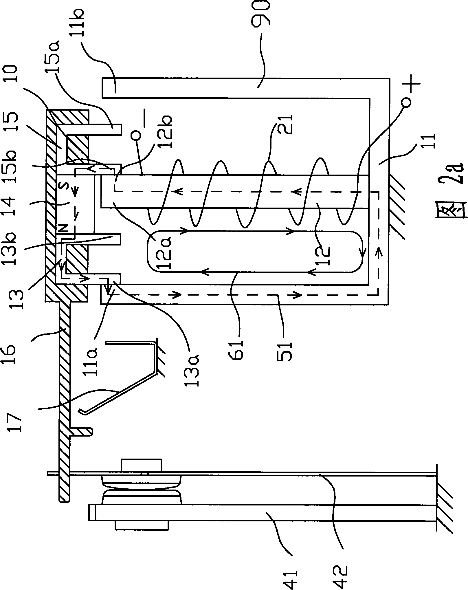
[0032] Embodiment 1, as shown in Fig. 2a and Fig. 2b, a magnetic latching relay of the present invention includes a magnetic circuit part, a contact part, and a counter force reed, and the magnetic circuit part, the contact part, and the counter force reed are relatively fixed. The magnetic circuit part is provided with a coil 21 , an E-shaped stationary magnetizer part 90 and a movable magnetizer part 10 . The E-shaped static magnetic conductor part 90 is formed by connecting the U-shaped magnetic conductor 11 and the strip-shaped magnetic conductor 12, the coil 21 is wound on the strip-shaped magnetic conductor 12, and an insulating material is arranged between the strip-shaped magnetic conductor 12 and the coil 21 layer, the insulating material can be injection molded together with the strip-shaped magnetic conductor 12 , and can also be wrapped or coated on the strip-shaped magnetic conductor 12 . The movable magnetizer component 10 is composed of two inverted U-shaped (ie...
Embodiment 2
[0033] Embodiment 2, referring to FIG. 3 , a magnetic latching relay of the present invention differs from Embodiment 1 in that the stationary magnetizer part 90 is composed of two U-shaped structure magnetizers 11, and the two U-shaped structure conductors The magnets 11 are joined together.
Embodiment 3
[0034] Embodiment 3, as shown in FIG. 4, a magnetic latching relay of the present invention differs from Embodiment 1 in that the movable magnetizer 13 and the movable magnetizer 15 of the movable magnetizer parts are opened upward U-shaped structure.
PUM
 Abstract
Description
Claims
Application Information