Central cross beam connecting type hinging framework

A connected, beam technology, applied in the direction of bogies, railway car body parts, transportation and packaging, etc., to achieve the effect of optimized design, low manufacturing cost, and reduced design difficulty

Inactive Publication Date: 2009-10-28
CRRC QINGDAO SIFANG CO LTD
View PDF0 Cites 20 Cited by
  • Summary
  • Abstract
  • Description
  • Claims
  • Application Information

AI Technical Summary

Problems solved by technology

[0004] The object of the present invention is to provide a central beam connection type hinged frame to solve the existing above-mentioned problems and defects

Method used


Image

  • Central cross beam connecting type hinging framework
  • Central cross beam connecting type hinging framework

Examples


Embodiment 1

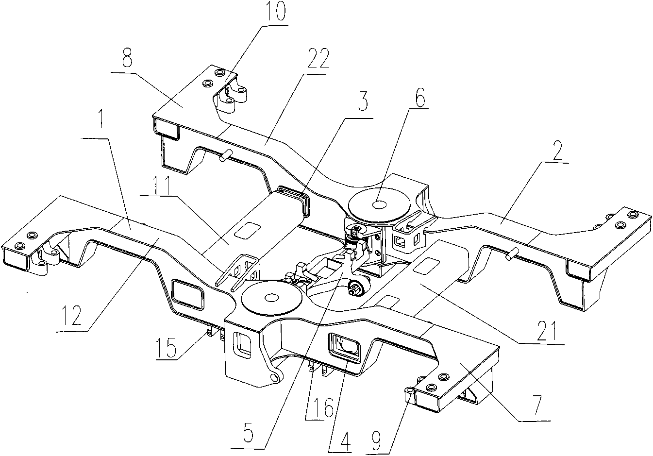
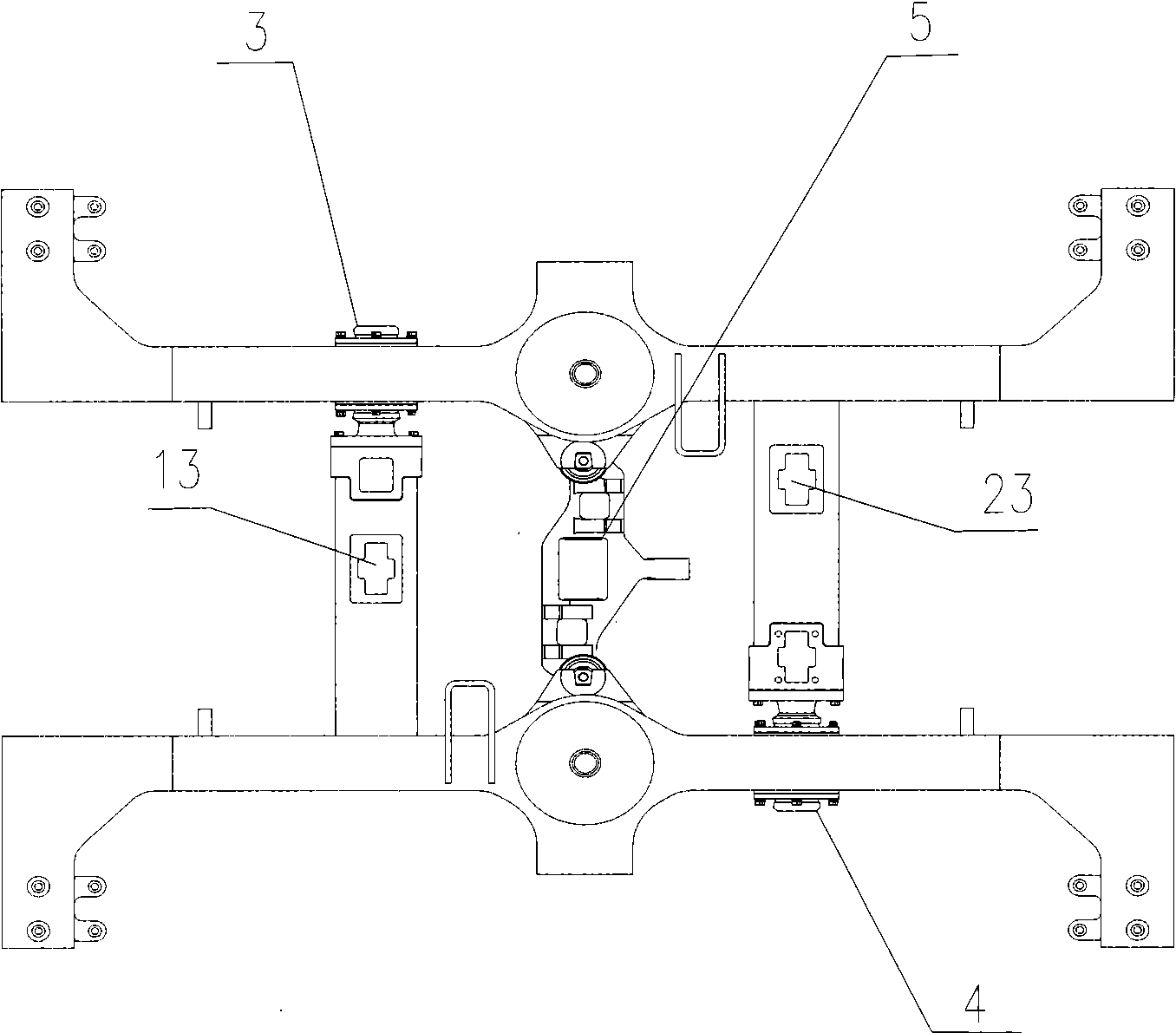
[0022] Example 1, such as figure 1 and figure 2 As shown, the central crossbeam-connected hinged frame includes two T-shaped frames 1 and 2 that are hinged to each other. in,

[0023] The frame 1 has vertically connected and integrally formed cross beams 11 and side beams 12 , and the frame 2 has vertically connected and integrally formed cross beams 21 and side beams 22 .

[0024] The crossbeams 11 run through the sidebeams 22, and are fixedly connected with each other by a bearing-type hinged structure 3. The crossbeams 21 run through the sidebeams 12 and are fixedly connected with each other by a bearing-type hinged structure 4 . The hinge structure 3 and the hinge structure 4 are arranged diagonally on the inner side of the frame.

[0025] The central beam 5 is respectively connected to the side beam 12 and the side beam 22 through elastic nodes at both ends, and the central beam 5 is arranged between the beam 11 and the beam 21 .

[0026] On the crossbeam 11, a moto...


PUM


Abstract

The invention relates to a central cross beam connecting type hinging framework, which enables the framework to realize flexible design on hinging points by two mutually-hinged T-shaped frames to be suitable for the track curve with an abrupt corner, therefore, the bearing limitation of the framework on torsion force is improved, and the design difficulty of a steering framework and the requirement on the material are lowered. Cross beams of the two frames are mutually articulated with side beams, and two hinging points are arranged on the diagonal line in the whole body of the framework. A central cross beam is respectively connected with side beams of the two frames by elastic panel nodes on two ends. As the characteristic of the scheme, when vehicle wheels travel on the track curve with an abrupt corner, the two hinging structures of the inner sides of the framework can bear higher torsion to be properly distorted for randomly protecting the framework. The cross beam is arranged between the cross beams of the two T-shaped frames, the cross beams and the side beams of the two frames are formed into a whole, and the cross beams between the two frames penetrate the side beams and are mutually hinged by a bearing-type hinging structure.

Description

technical field [0001] The invention relates to a bogie frame for rail vehicles and belongs to the field of mechanical manufacturing. Background technique [0002] At present, the rail vehicle bogies used in railway trains, subways and light rail transportation generally adopt integral rigid structures. Due to the influence and limitation of the wheel-rail line of the vehicle, when the wheel set travels to a curve with a sharper corner, the outer side of the rigid frame and the part close to the wheel set will bear a large torque. At the same time, when the vehicle speed is high, the connection between the frame and the primary suspension device will also be subject to a greater impact. [0003] Adopting the above-mentioned existing rigid frame has higher requirements on the manufacturing quality and material of the frame, which correspondingly increases the overall design difficulty and manufacturing cost of the bogie. Contents of the invention [0004] The object of th...

Claims


Application Information

Patent Timeline
Patent Type & Authority Applications(China)
IPC IPC(8): B61F5/52B61F5/00
Inventor 宋晓文李言义张洪
Owner CRRC QINGDAO SIFANG CO LTD
Why Eureka
Try Eureka