Vehicle middle pillar structure

A pillar structure and vehicle technology, applied in the superstructure, vehicle parts, vehicle safety arrangement, etc., can solve the problems of increasing the size and weight of the inner panel, and achieve the effect of improving rigidity, improving rigidity, and improving driving safety

Inactive Publication Date: 2009-10-28
SUZUKI MOTOR CORP
View PDF2 Cites 12 Cited by
  • Summary
  • Abstract
  • Description
  • Claims
  • Application Information

AI Technical Summary

Problems solved by technology

For this reason, the width (length) of the inner panel in the length direction of the vehicle becomes large, thereby increasing the size of the inner panel and the weight of the vehicle

Method used


Image

  • Vehicle middle pillar structure
  • Vehicle middle pillar structure
  • Vehicle middle pillar structure

Examples


Embodiment Construction

[0036] Hereinafter, exemplary embodiments of the present invention are described with reference to the accompanying drawings.

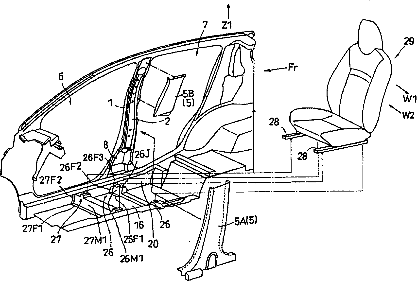
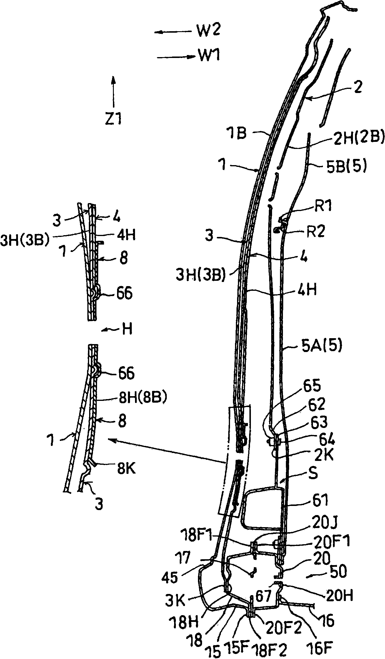
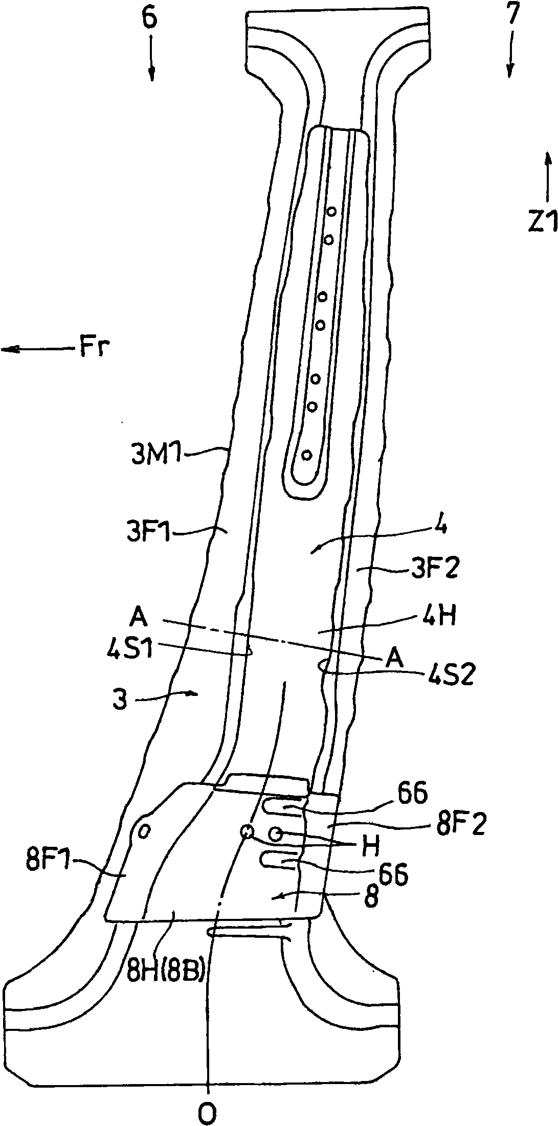
[0037] Figures 1 to 5 A vehicle (automobile) center pillar structure is shown, including an outer panel 1 , an inner panel (center pillar inner panel) 2 , a first reinforcement member 3 , a second reinforcement member 4 , and a center pillar trim 5 . The central pillar has a configuration in which the outer panel 1, the inner panel 2, the first reinforcement member 3, the second reinforcement member 4, and the intermediate pillar modification 5 extend in an obliquely vertical direction so that the upper end is more dense than the lower end. Slightly closer to the rear of the vehicle. The middle pillar modification 5 includes a lower modification 5A and an upper modification 5B separated from each other. Such as figure 2 As shown, the upper end-side joining portion R1 of the lower modification 5A is joined to the lower end-side joining portion R2 ...


PUM


Abstract

The invention provides a vehicle middle pillar structure which has an outer plate, an inner plate and a first reinforcement member. The first reinforcement member has a protuberance part, a front flange and a rear flange; the front flange is welded onto the front edge of the inner plate to form a first coupling part; the rear flange is welded onto the rear edge of the inner plate to form a second coupling part; The front flange is provided with a front extension part which extends from the first coupling part to the front side of the vehicle; The rear flange is provided with a rear extension part which extends from the second coupling part to the back side of the vehicle; and both the front and the rear extension part are welded onto the outer plate.

Description

[0001] This application claims priority from Japanese Patent Application No. 2008-111303 filed on April 22, 2008, the entire contents of which are hereby incorporated by reference. technical field [0002] The invention relates to a vehicle center pillar structure, which includes an outer panel, an inner panel, and a reinforcement member. Background technique [0003] In the related art of the center pillar structure provided in the vehicle, each of the reinforcing member, the outer panel and the inner panel is formed to have a hat-like section, including a front side flange formed on the front side of the vehicle, a front side flange formed on the rear side of the vehicle side rear flanges and a raised portion formed therebetween. The front flanges of the reinforcing member are inserted between the front flanges of the outer panel and the front flanges of the inner panel so that the three pieces of the front flanges are integrally welded to be connected to each other. The ...

Claims


Application Information

Patent Timeline
Patent Type & Authority Applications(China)
IPC IPC(8): B62D25/04B60R21/02
Inventor 米田伸
Owner SUZUKI MOTOR CORP
Why Eureka
Try Eureka