
Radio frequency identification device and method

A radio frequency identification device and radio frequency identification technology, applied in the field of radio frequency, can solve problems such as unfavorable promotion and application, inconvenient use, limited functions, etc., and achieve the effect of facilitating popularization and application and reducing costs

Inactive Publication Date: 2009-10-28
POTEVIO INFORMATION TECH CO LTD
View PDF2 Cites 3 Cited by
  • Summary
  • Abstract
  • Description
  • Claims
  • Application Information

AI Technical Summary

Problems solved by technology

This solution does not need to modify the existing mobile phone, so it can overcome the problems of high cost and poor versatility of the previous type of solution
However, due to the limited functions integrated in the card, only one of the forms can be selected, that is, either the form of a radio frequency reader or the form of a radio frequency tag, and since the two forms cannot exist at the same time, it is impossible to use one memory card to realize two function, if the user needs both the RF tag function and the RF reader function, he must have another memory card embedded in the RF reader function module or the RF tag function module at the same time, so the user is inconvenient to use and is not conducive to popularization and application.
[0006] It can be seen that the existing technical solutions that combine RFID technology with mobile phones have problems such as high cost and unfavorable promotion and application

Method used


Image

  • Radio frequency identification device and method
  • Radio frequency identification device and method
  • Radio frequency identification device and method

Examples


Embodiment Construction

[0034] In order to make the purpose, technical solution and advantages of the present invention clearer, the present invention will be further described in detail below in conjunction with the accompanying drawings and specific embodiments.

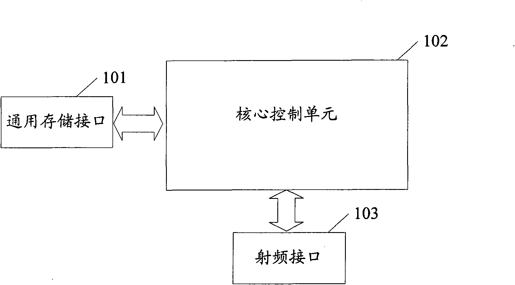
[0035] The main idea of ​​the present invention is to control the working state of the radio frequency identification device by setting the radio frequency control unit, so that the device can switch between the two working states of the radio frequency tag and the radio frequency reader according to the needs, and realize the radio frequency tag and the radio frequency identification device. The two functions of the radio frequency reader are integrated in the same device.

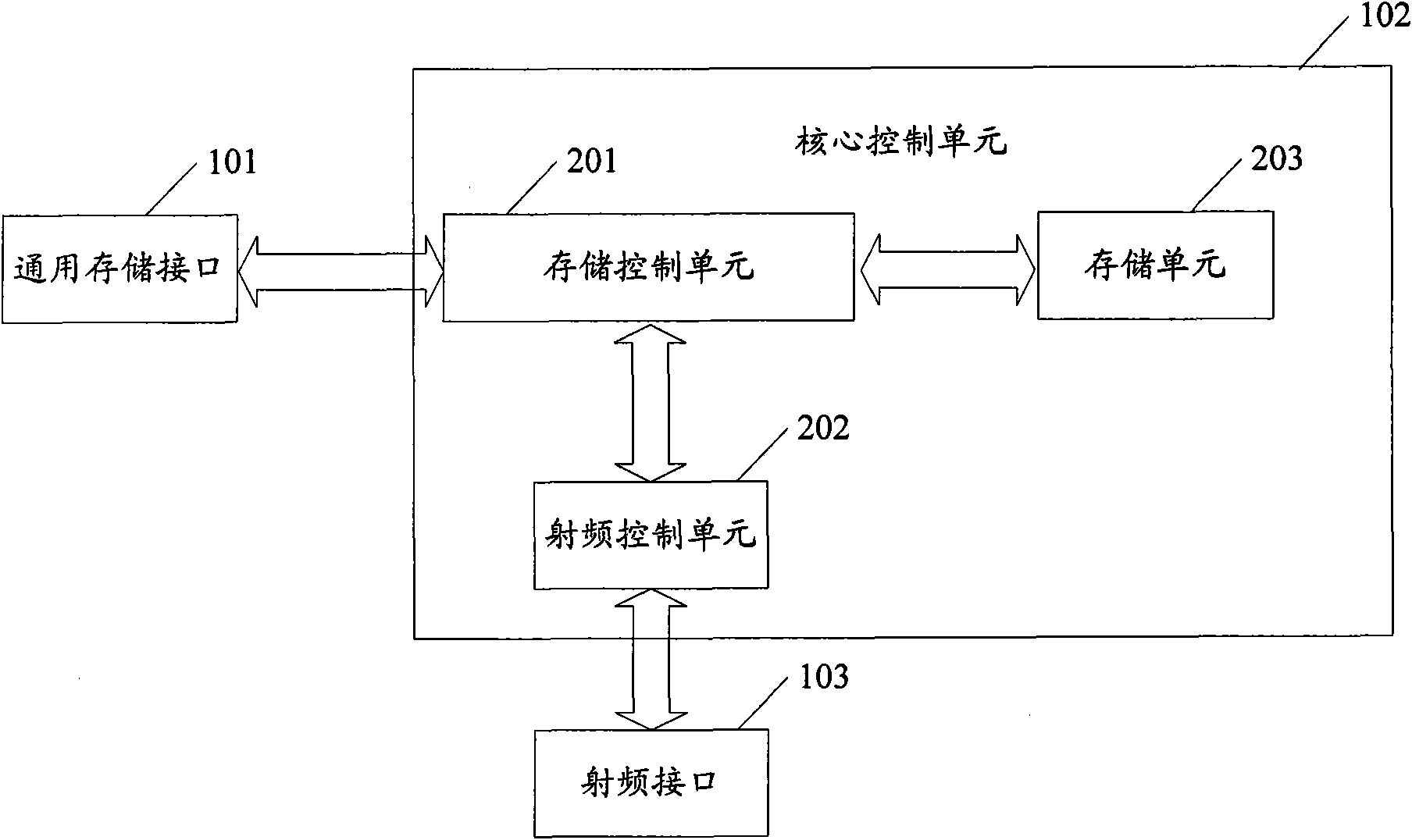
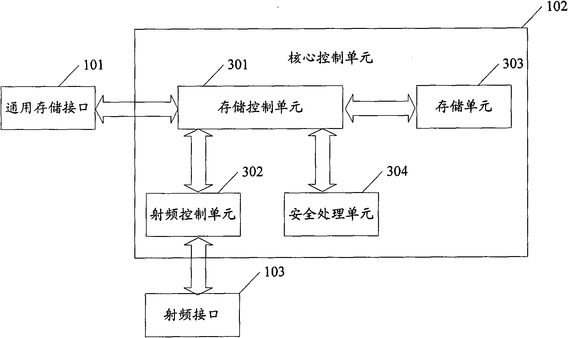
[0036] figure 1 It is a structural schematic diagram of the present invention. Such as figure 1 As shown, the present invention mainly includes: a general storage interface 101, a core control unit 102, and a radio frequency interface 103; the general storage inter...


PUM


Abstract

The invention discloses a radio frequency identification device, comprising a radio frequency interface, a core control unit and a general memory interface; the radio frequency interface and the general memory interface are connected with the core control unit respectively; the core control unit is used for receiving the radio frequency identification instructions from other radio frequency identification devices or portable terminal equipment within the prearranged range by the general memory interface or the radio frequency interface, and carries out corresponding radio frequency identification processing according to the radio frequency identification instruction and the current working state of the device; when the instruction is a working state shifting instruction, the working state of the device is shifted; the working state is a radio frequency label state or a radio frequency reading state; the radio frequency interface is used for realizing the information interaction between the core control unit and other radio frequency identification devices within the prearranged range; and the general memory interface is used for realizing the information interaction between the portable terminal equipment and the core control unit. The device can integrate two functions of a radio frequency label and a radio frequency reader.

Description

technical field [0001] The invention relates to radio frequency technology, in particular to a radio frequency identification device and method. Background technique [0002] At present, radio frequency identification (RFID) technology has a very wide range of applications. It can be used for electronic wallets and various tickets, which is safe and convenient; it can also be used to identify objects to achieve anti-counterfeiting purposes; it can also replace trademarks and provide Trademarks and various information other than trademarks. The existing radio frequency identification technology needs to be realized by two parts: radio frequency tags and radio frequency readers. Among them, since radio frequency readers are composed of RFID reading chips, antennas, microprocessors, displays, memories, buttons, casings and power supplies, the cost is relatively high. Generally, only units or specialized service agencies are equipped, and cannot be popularized to most consumers...

Claims


Application Information

Patent Timeline
Patent Type & Authority Applications(China)
IPC IPC(8): G06K7/00G06K19/07
CPCG06K19/07G06K7/00G06K7/0008G06K7/10297H04L12/00H04B5/00H04L69/32
Inventor 张宇宏王小军姚彬常莹刘道斌李力争杨木祥刘宏伟
Owner POTEVIO INFORMATION TECH CO LTD
Learn More