Iris rotating artificial eye and manufacturing method thereof

A rotary, iris technology, applied in the field of medical devices, can solve problems such as poor exercise effect, sunken eyes, narrow eyelid fissures, etc.

Inactive Publication Date: 2011-08-17
四川省医学科学院
View PDF0 Cites 0 Cited by
  • Summary
  • Abstract
  • Description
  • Claims
  • Application Information

AI Technical Summary

Problems solved by technology

However, the prosthetic eye is inlaid in front of the prosthetic eye platform by means of a radian. When the prosthetic eye is relatively thick, the movement power is insufficient, and the space resistance is too large, so the movement effect is not good.
[0003] The internal contradiction of the product is the contradiction between the fullness of the eyelid and the movement of the prosthetic eye: 1: When the prosthetic eye is large, the eyelid is full and the bilateral symmetry is good, but the activity decreases. Generally speaking, the prosthetic eye will not rotate, so the patient When looking at other directions, the prosthetic eye cannot rotate accordingly, resulting in asymmetrical eye position and poor cosmetic effect
2: Conversely, when the prosthetic eye is small, the motion of the prosthetic eye is better, but the affected eye is sunken, the palpebral fissure is narrow, and the eyes are obviously asymmetrical
However, the rod-shaped link design has the problem of being clinically impractical, and has been eliminated in clinical practice; the magnetic drive design scheme has no products yet, but there are many theoretical problems in medicine, magnetism, and physics, which cannot be practically applied.
Therefore, there is currently no better way to solve the contradiction between the size of the artificial eye and the movement of the artificial eye at home and abroad.

Method used


Image

  • Iris rotating artificial eye and manufacturing method thereof
  • Iris rotating artificial eye and manufacturing method thereof
  • Iris rotating artificial eye and manufacturing method thereof

Examples


Embodiment Construction

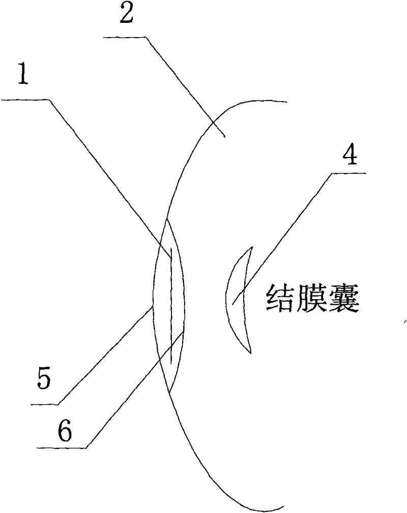
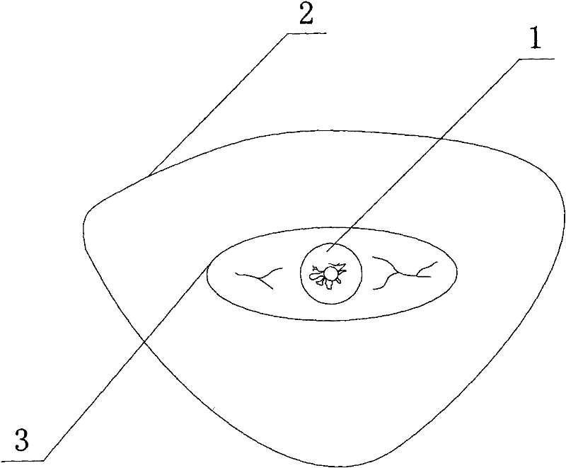
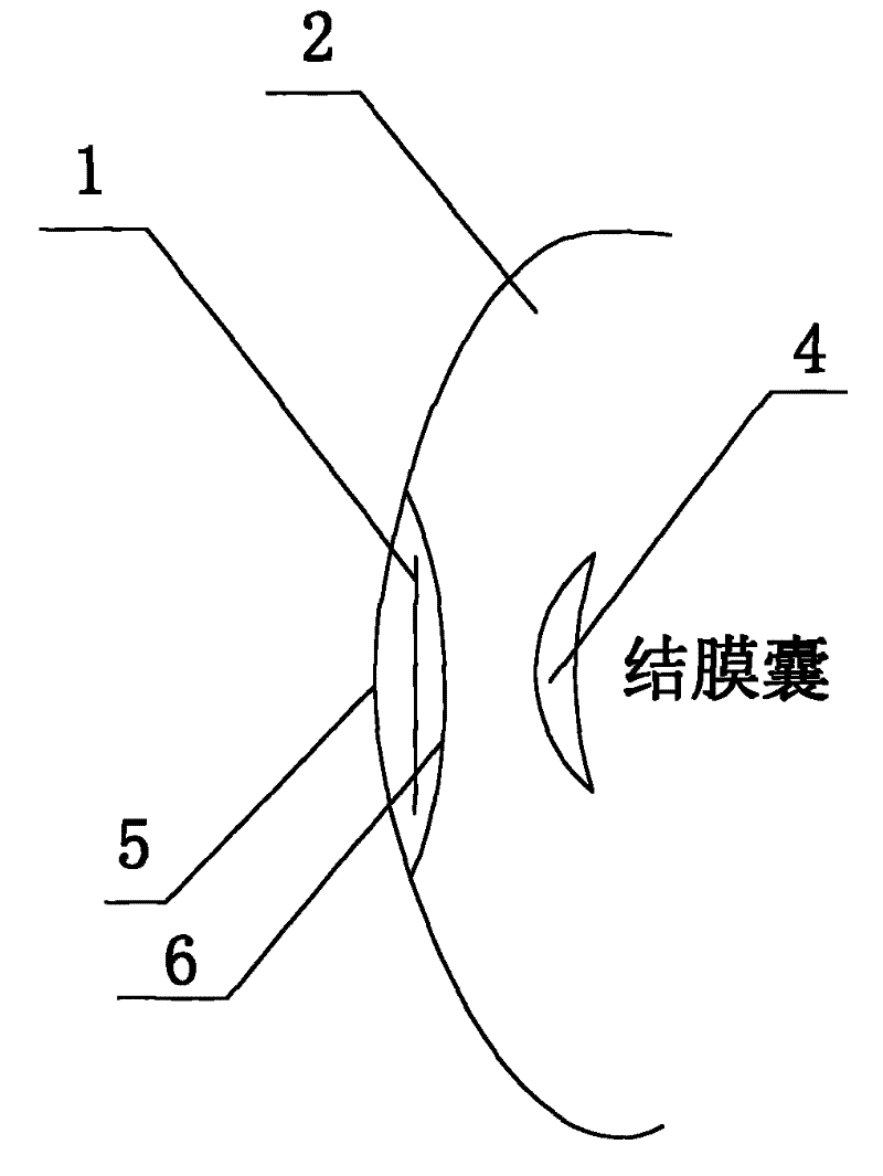
[0019] refer to figure 1 , figure 2 , an iris rotating prosthetic eye, including a prosthetic eye, said prosthetic eye is made up of a support part 2, a core part 3, a magnetic force drive piece 4, and an iris film 1, wherein the support part 2 is made of silicone rubber or other polymer materials , a hole corresponding to the size of the core part 3 is provided on it, and the core part 3 is fixed therein. The iris membrane 1 is arranged in the core part 3 , and the magnetic driving piece 4 is arranged in the conjunctival sac and is located directly behind the core part 3 at the same time.

[0020] Wherein, the core part 3 is a sandwich structure formed by sealing two smooth arc-shaped partitions, and the gap between the front and rear partitions is 0.2-2.0mm.

[0021] The front partition is made of transparent polymer material, with a height of 8-10mm, a width of 27-32mm, and a thickness of 0.1-2.0mm. ~32mm, thickness 0.1~2.0mm, milky white with a little brown (simulating...


PUM

PropertyMeasurementUnit
diameteraaaaaaaaaa
diameteraaaaaaaaaa
diameteraaaaaaaaaa

Abstract

The invention discloses an iris rotating artificial eye and a manufacturing method thereof. The artificial eye is designed into a hollow thin layer, an interlayer structure is arranged in the artificial eye, and an iris membrane is arranged in the interlayer structure of the artificial eye, wherein a magnetic driving sheet similar to a cornea contact lens sample is placed into a conjunctival sac on the back of the artificial eye to drive the iris membrane to move. The contradiction problem in the prior artificial eye, namely the relation between the size and motion degree of the artificial eye, is solved, so the artificial eye can meet the requirements of eyelid plumpness and the simulated motion of the artificial eye at the same time.

Description

technical field [0001] The invention belongs to the technical field of medical devices, in particular to an artificial eye directly implanted into the conjunctival sac. Background technique [0002] At present in our country, due to various reasons, about 30,000 patients need eyeball enucleation every year. With the improvement of people's living standards, patients have higher and higher demands for beauty after eyeball removal, but this demand has been ignored by doctors and society. At present, the design and production of prosthetic eyes remain at the level of individual workshops. Due to the limitations of materials and basic design concepts, the current products are not satisfactory in terms of beauty. In principle, the prosthetic eye has two cosmetic functions: 1 is to support the eyelid, maintain the normal size of the palpebral fissure and the convexity of the upper eyelid; 2 is to simulate the rotation of the eyeball and move synchronously with the opposite eyebal...

Claims


Application Information

Patent Timeline
Patent Type & Authority Patents(China)
IPC IPC(8): A61F2/14A61L27/16
Inventor 樊映川曲超
Owner 四川省医学科学院
Why Eureka
Try Eureka