1/2 type tandem-blade type transonic speed centrifugal impeller

A centrifugal impeller and transonic technology, applied in non-variable pumps, machines/engines, components of pumping devices for elastic fluids, etc., can solve the problems of low efficiency of the whole stage and narrow stable operating range, and achieve Improve the efficiency of the whole stage, expand the surge margin, and increase the effect of blocking flow

Inactive Publication Date: 2009-11-11
XI AN JIAOTONG UNIV
View PDF0 Cites 13 Cited by
  • Summary
  • Abstract
  • Description
  • Claims
  • Application Information

AI Technical Summary

Problems solved by technology

[0006] The present invention provides a 1 / 2 type tandem blade type transonic centrifugal impeller in order to solve the problems of narrow stable operating range and low whole-stage efficiency of the existing centrifugal impeller in transonic flow

Method used


Image

  • 1/2 type tandem-blade type transonic speed centrifugal impeller
  • 1/2 type tandem-blade type transonic speed centrifugal impeller
  • 1/2 type tandem-blade type transonic speed centrifugal impeller

Examples


Embodiment 1

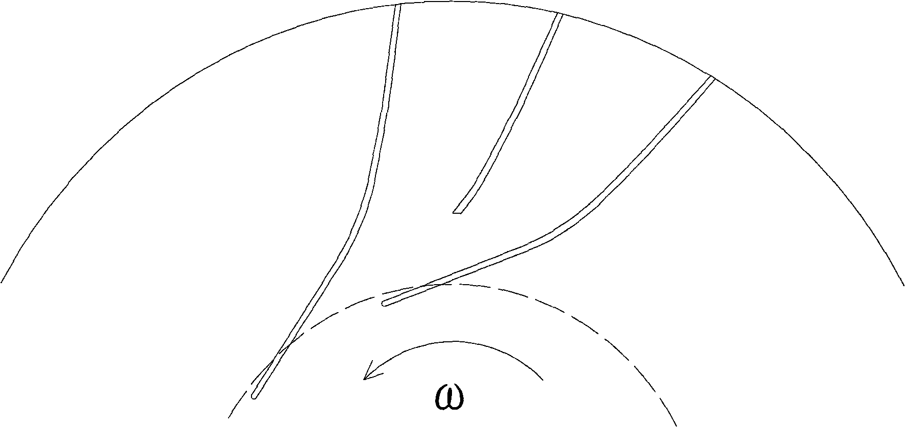
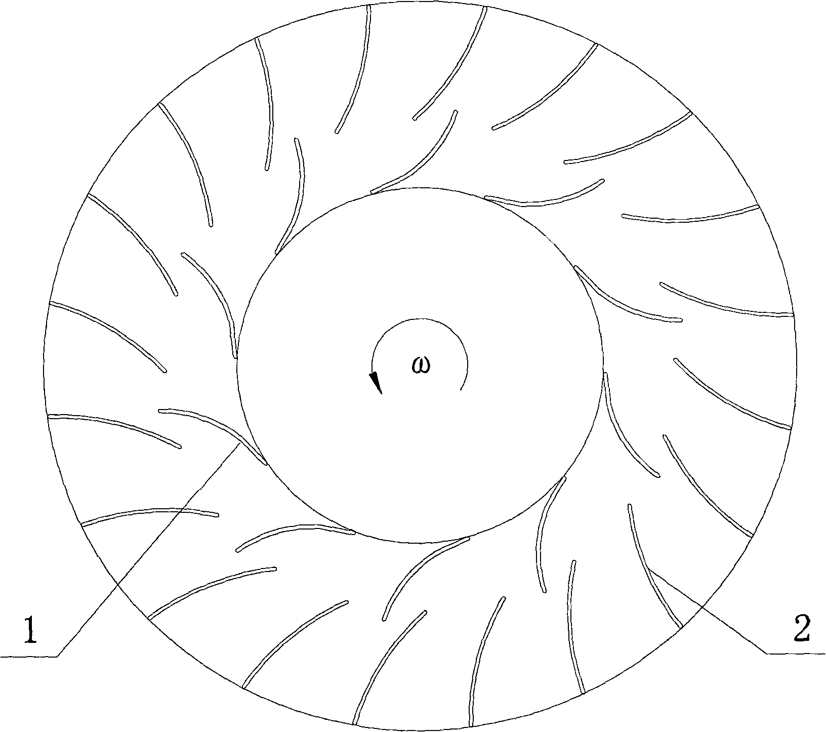
[0026] Embodiment 1, the rear row of blades 2 overlaps the front row of blades 1, and when the degree of overlap Δm=30%, the staggered degree Δθ of the rear row of blades and the front row of blades is 5%, and the relative division position m of the rear row of blades and the front row of blades 20%.

Embodiment 2

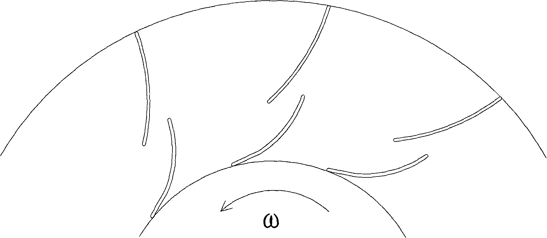
[0027] Embodiment 2, the inlet of the rear row of blades 2 is flush with the outlet of the front row of blades 1, that is, when Δm=0%, the staggered degree Δθ of the rear row of blades and the front row of blades is 25%, and the staggered degree Δθ of the rear row of blades and the front row of blades is 25%. The relative division position m is 50%.

Embodiment 3

[0028] Embodiment three, when rear row of blades 2 and front row of blades 1 overlap degree Δm=-5% (not overlapping), the degree of staggering Δθ of rear row of blades and front row of blades is 45%, the relative of rear row of blades and front row of blades The division position m is 80%.


PUM


Abstract

The invention discloses a 1 / 2 type tandem-blade type transonic speed centrifugal impeller, which comprises an inducer consisting of a front row of blades and a guide wheel consisting of a back row of blades, wherein the front and the back rows of the blades have three-dimensional distorted shapes and are divided, staggered and overlapped with one another. The centrifugal impeller is characterized in that the number ratio of the front row of the blades to the back row of the blades is 1:2. In the centrifugal impeller, the front row of the blades are arranged with low consistency and the back row of the blades are arranged with high consistency so that the effective through-flow area is enlarged and the blockage flow is increased; and the evenness of the flow at the outlet of the impeller is improved so that the wake losses and the shock losses between the impeller and a diffuser are reduced, the efficiency of the whole stage is improved, and the surge margin is enlarged.

Description

technical field [0001] The invention relates to a centrifugal impeller, in particular to a tandem blade type transonic centrifugal impeller with a number ratio of front and rear blades of 1:2. Background technique [0002] Centrifugal compressor is a kind of rotary impeller machinery, which is widely used in aerospace, metallurgical power, petrochemical industry, energy power and other fields. Its main function is to provide continuous, stable and flow The high-pressure gas environment meets the needs of process flow and chemical reaction for gas pressure and flow. The basic principle of the centrifugal compressor to increase the gas pressure is: the rotating centrifugal impeller converts the mechanical energy of the rotating shaft into the pressure energy and kinetic energy of the gas through the centrifugal force; the diffuser further converts part of the kinetic energy into pressure energy; the air flow or through the volute Export the centrifugal compressor, or enter th...

Claims


Application Information

Patent Timeline
IPC IPC(8): F04D29/30
Inventor 张楚华袁丹妮
Owner XI AN JIAOTONG UNIV
Why Eureka
Try Eureka