Automatic distributing mechanism of connector posts for wire connecting terminal

A technology of distributing mechanism and terminal, which is applied in the field of automatic distributing structure, can solve the problems of easily stuck materials occupying an area, reduce the speed of terminal, increase the auxiliary time, etc., achieve convenient cleaning and maintenance, reduce error rate, structure simple effect

Active Publication Date: 2009-11-18
JIANG MEN TOP ELECTRIC INTELLIGENCE
View PDF0 Cites 23 Cited by
  • Summary
  • Abstract
  • Description
  • Claims
  • Application Information

AI Technical Summary

Problems solved by technology

For the occasions where the wiring post workpiece is divided and the automatic production of the assembly line has not been realized, manual loading and unloading is adopted, which not only increases the labor intensity, but also increases the auxiliary time, and reduces the speed at which the binding post enters the next process; for this reason, people began Study how to implement a reliable and efficient automatic loading and unloading method
The current common automatic material distribution operation mechanism for terminal posts has the defects of complex structure, loud noise during material distribution, easy material jamming, large floor space, and high error rate.

Method used


Image

  • Automatic distributing mechanism of connector posts for wire connecting terminal
  • Automatic distributing mechanism of connector posts for wire connecting terminal
  • Automatic distributing mechanism of connector posts for wire connecting terminal

Examples


Embodiment 1

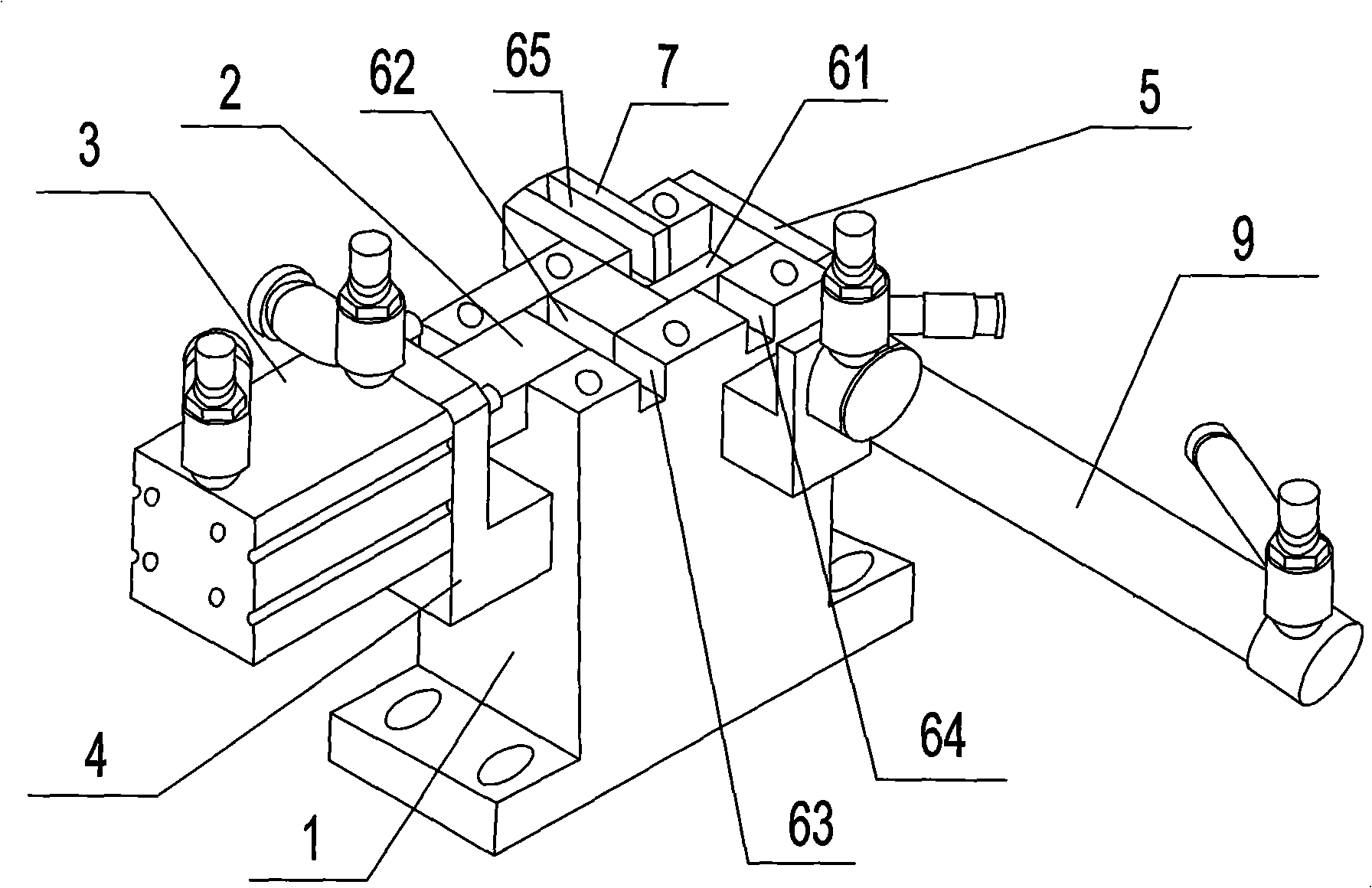
[0024] Such as figure 1 As shown, an automatic distributing mechanism for wiring terminals for wiring terminals is used to screen the entire batch of wiring terminal workpieces 8 to separate individual individuals with qualified lengths and then send them to the next process. Institutions include:

[0025] --Distributing base; along the longitudinal direction of the distributing base 1, there is a transverse groove 61, the width of the transverse groove is the upper limit size of the qualified length of the terminal; the vertical distributing base has a conduction on the longitudinal direction of the distributing base Push chute 63 with transverse groove;

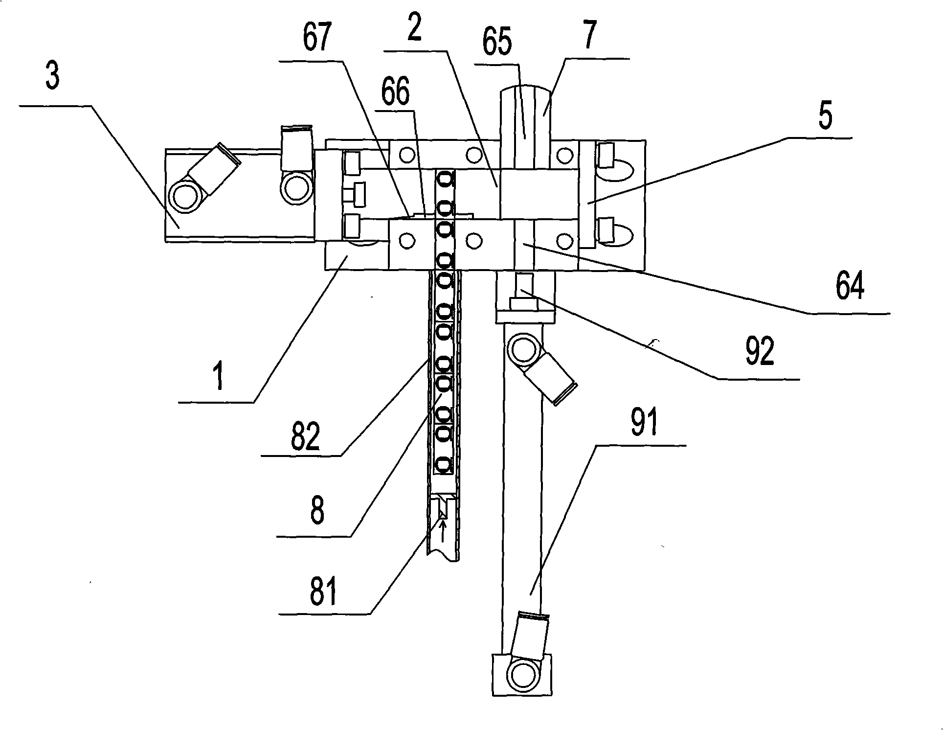
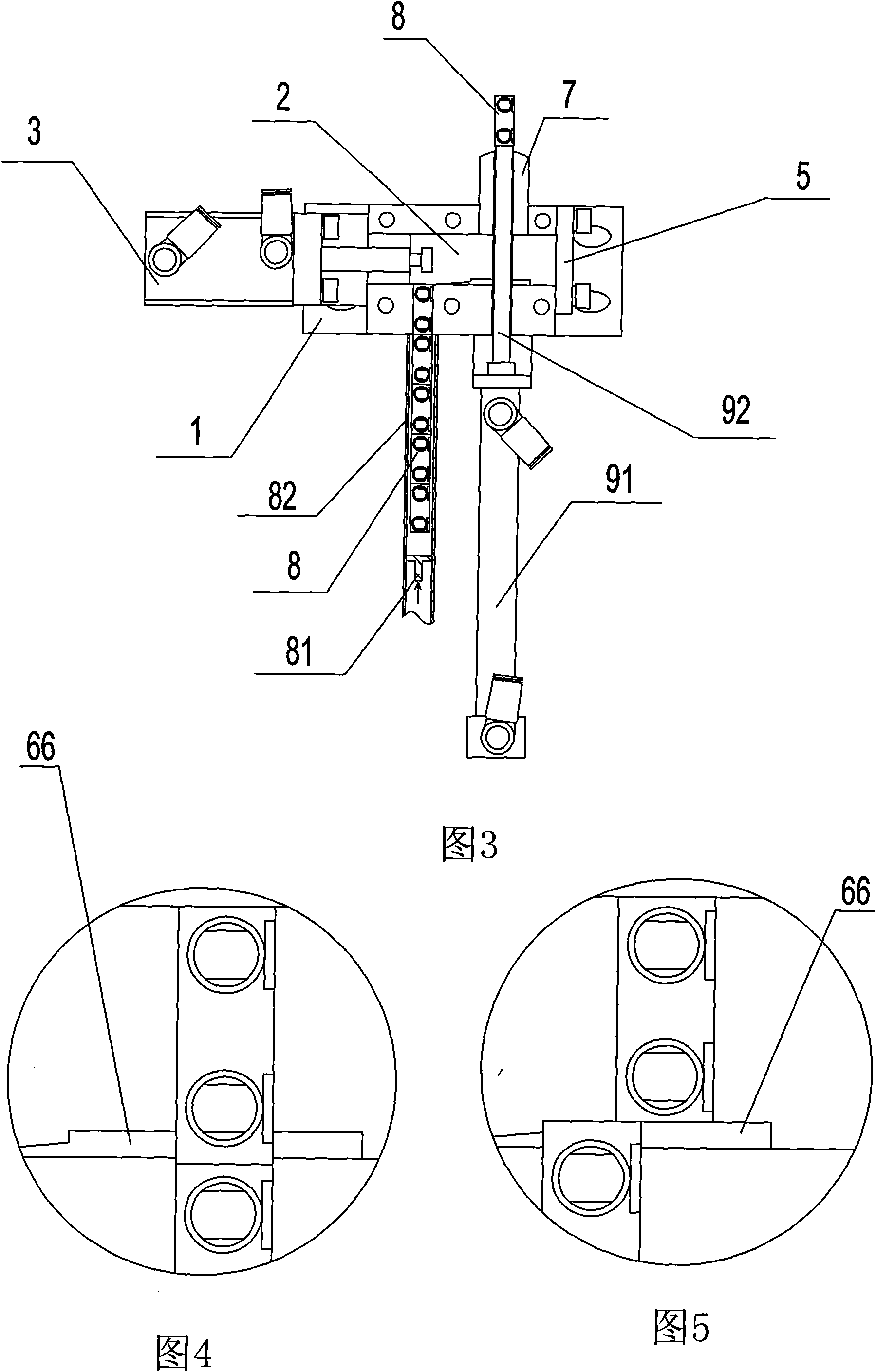
[0026] --Feeding device, which can be movably inserted into the base, includes a guide groove 82 for accommodating a row of terminal posts. The discharge end of the guide groove is correspondingly joined to the pusher groove; the other end of the guide groove is provided with a pusher terminal row Pushing device 81 advancing a...

Embodiment 2

[0034] This embodiment 2 uses different limit devices to limit the movement of the slider on the basis of embodiment 1. The limit device of this embodiment 2 is that the end surface of the pusher cylinder seat facing the slider is used as the slider in the transverse direction. The front limit of the movement in the groove, the side of the distributing base away from the pushing cylinder serves as the rear limit of the sliding block moving in the transverse groove, that is, the transverse groove only leads to one end of the distributing base.


PUM


Abstract

The invention discloses an automatic distributing mechanism of connector posts for wire connecting terminals, which comprises a distributing base, a feeding device, and a distributing device; a transverse groove is arranged in the length direction of the distributing base, and a pushing groove communicating the transverse groove is arranged on the distributing base vertical to the length direction of the distributing base; the feeding device comprises a guide slot used for accommodating a connector post row to pass through, and the other end of the guide slot is provided with a pushing device for pushing the connector post row to advance along the guide slot; the distributing device is fixedly arranged on one side of the distributing base, and comprises a pushing cylinder block connected with the distributing base; a pushing cylinder is arranged on the pushing cylinder block, and the action end of the pushing cylinder is connected with a slide block which is inserted into the transverse groove in a matching way; the slide block is provided with a longitudinal groove matched with the specification of workpieces of the connector posts; and the lateral surface of the slide block facing the pushing groove is provided with a two-step step-like limit groove which is arranged close to the lateral surface of the longitudinal groove of the pushing cylinder. The mechanism has simple structure, and realizes the feeding and the distributing of the connector posts through less cylinders and one slide block.

Description

Technical field: [0001] The invention relates to an automatic material distributing structure, in particular to a material distributing mechanism which is specially used for the terminal work piece of the terminal to screen the terminal of the qualified length. Background technique: [0002] At present, in the industrialized automatic production process of terminal blocks, it is often necessary to separate the entire row of terminal work pieces into a single terminal unit with a qualified length for use in the next step. Generally, in the case that there is no automatic assembly line for terminal blocks, the sorting of terminal parts is usually done by manual screening. For the occasions where the terminal workpiece is divided and the assembly line is not automated, manual loading and unloading is adopted, which not only increases the labor intensity, but also increases the auxiliary time, and reduces the speed of the terminal to enter the next step; for this reason, people start...

Claims


Application Information

Patent Timeline
Patent Type & Authority Applications(China)
IPC IPC(8): H01R43/00H01R43/20B07C5/04
Inventor 饶小坡
Owner JIANG MEN TOP ELECTRIC INTELLIGENCE
Why Eureka
Try Eureka