Deformation method based on control meshes

A technology for controlling grids and vertices, applied in 3D image processing, 2D image generation, image data processing, etc., can solve the problem of increasing operation control grid cost, rough target model, and first-order discontinuity of interpolation function And other issues

Inactive Publication Date: 2009-11-25
ZHEJIANG UNIV
View PDF0 Cites 14 Cited by
  • Summary
  • Abstract
  • Description
  • Claims
  • Application Information

AI Technical Summary

Problems solved by technology

Although the local characteristics of barycentric coordinate interpolation are convenient for fast calculation and local control, when the control vertices are relatively sparse, due to the first-order discontinuous nature of the interpolation function, the target model will produce obvious non-smooth flaws at the boundary of the control mesh
Increasing the number and density of control vertices can weaken this effect, but correspondingly increases the cost of manipulating the control mesh

Method used


Image

  • Deformation method based on control meshes
  • Deformation method based on control meshes
  • Deformation method based on control meshes

Examples


Embodiment Construction

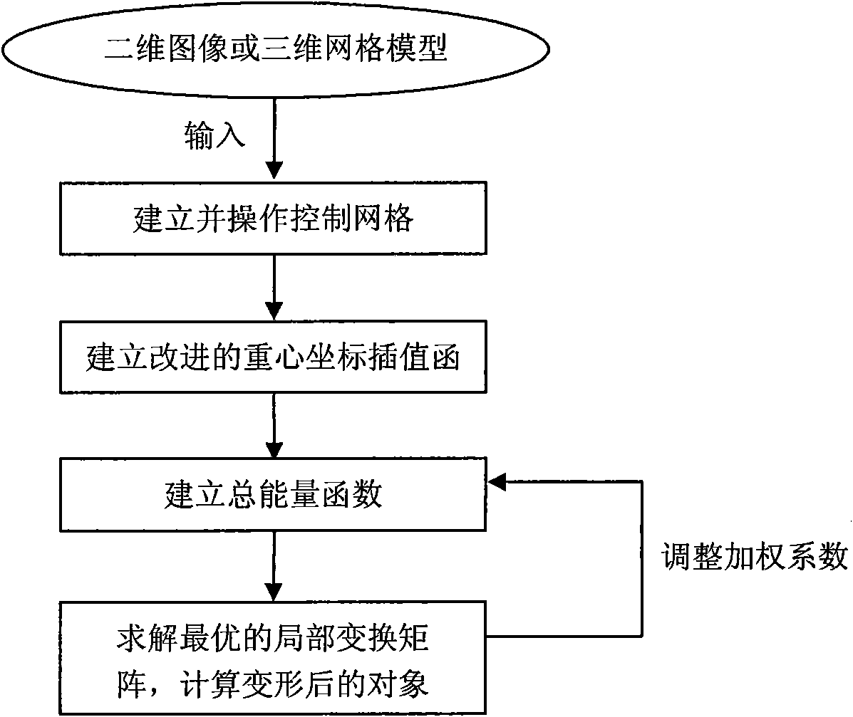
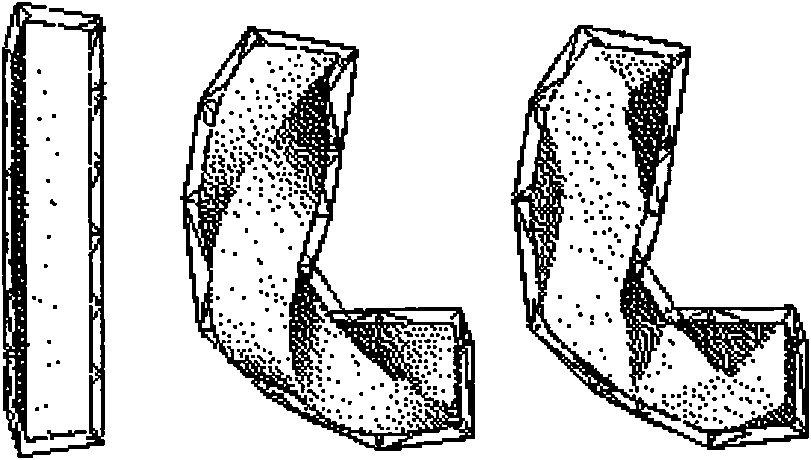
[0027] The purpose and effects of the present invention will become more apparent by describing the present invention in detail below with reference to the accompanying drawings.

[0028] Let Ω be R d The target object in space, d can be 2 or 3, Φ=(U, T) is a certain control grid of Ω, where U=(u 1 ,...,u n ) is the set of control vertices, T=(t 1 ,...,t m ) represents the collection of fragments of the grid. For two-dimensional space, d=2, Φ is a plane triangular grid. For three-dimensional space, d=3, Φ is a tetrahedral grid. x(u):Ω→R d is the transformation function of the control grid, and x(u i )=x i , ∀ u i ∈ U , Then the form of the traditional barycentric coordinate interpolation function is as follows:

[0029] x ( u ) = Σ i = ...


PUM


Abstract

The invention discloses a deformation method based on control meshes. The method calculates the deformation result corresponding to a target object through an improved areal coordinate interpolation technique according to the deformation of the control meshes. The invention is capable of generating visually smooth interpolation result through extremely sparse control meshes, regenerating the position of a control vertex, and performing local evaluation, and is suitable for realizing high-performance calculation using a graphic display card.

Description

technical field [0001] The invention relates to the technical field of digital geometry processing, in particular to a deformation method based on a control grid. technical background [0002] Nowadays, with the continuous development of digital acquisition technology, high-complexity 3D mesh models are becoming more and more popular, and the rapid and effective editing of complex objects has become a hot topic that has attracted widespread attention, and the shape editing of models will involve deformation technology. The method of deforming the mesh model is generally to use a control mesh that surrounds the model, which can be divided into two stages: operating control vertices and interpolation calculation. In the former stage, various methods are used to deform the control mesh according to the user's operation on the control vertices; in the latter stage, the deformation result of the embedded model is calculated according to the deformation interpolation of the contro...

Claims


Application Information

Patent Timeline
Patent Type & Authority Applications(China)
IPC IPC(8): G06T15/10G06T11/00
Inventor 黄劲陈禄刘新国鲍虎军
Owner ZHEJIANG UNIV
Why Eureka
Try Eureka