
Method and systems for allocating bandwidth

A bandwidth and bandwidth allocation technology, applied in transmission systems, radio transmission systems, electrical components, etc., can solve the problems of round-trip satellite link delay, VoIP communication jitter, long delay, etc., and achieve accelerated signaling and good bandwidth reuse. , reduce the effect of timeout

Inactive Publication Date: 2009-12-02
SIEMENS AG
View PDF1 Cites 5 Cited by
  • Summary
  • Abstract
  • Description
  • Claims
  • Application Information

AI Technical Summary

Problems solved by technology

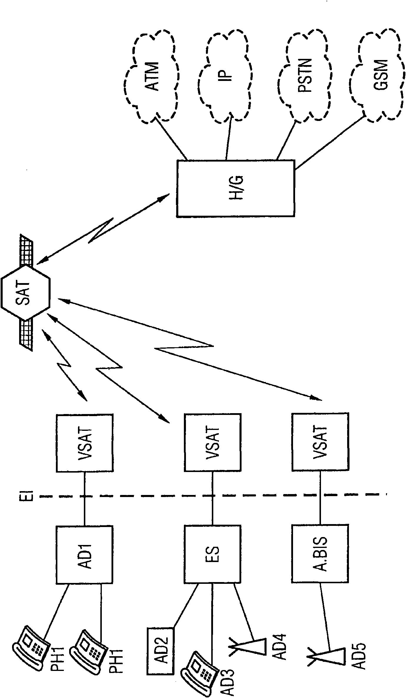
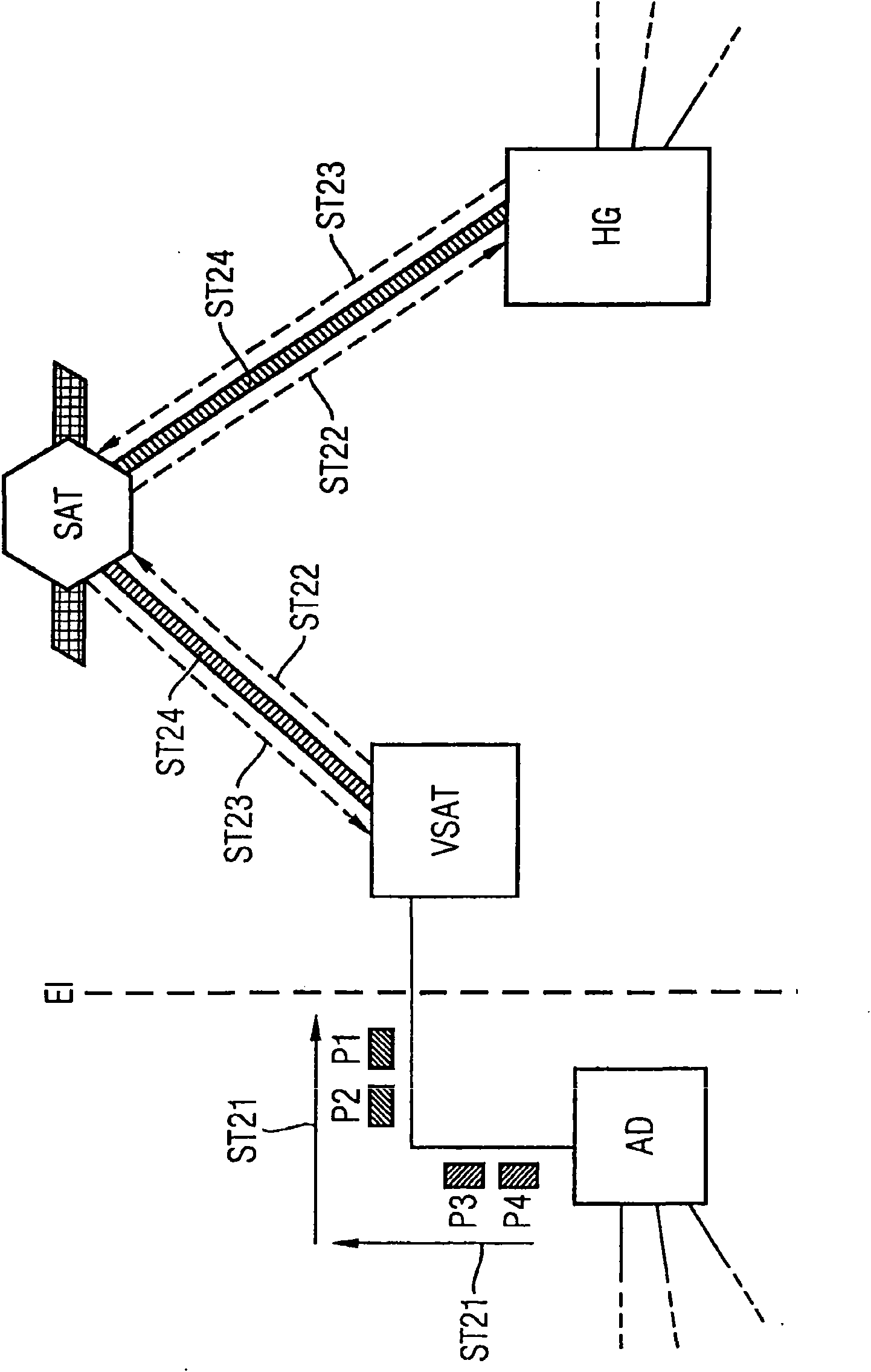
The main disadvantage of such a centralized bandwidth rate control method is that it implies round-trip satellite link delays for the bandwidth allocation to the remote stations to be done by the hub gateway, which is hereinafter schematically represented by FIGS. 1 to 5 is illustrated
In fact, the round-trip delay may be on the order of 500ms if propagation time alone is considered, but other factors may contribute to longer delays
Therefore, in the case of RDBC distribution, a first disadvantage is that during the start-up phase of the VoIP phase, the packets P1, ..., P4 arriving at the remote satellite station VSAT are in the input buffer (not shown) in the remote satellite terminal VSAT on, waiting for system reaction and bandwidth allocation, thus causing jitter at the start of VoIP communication
[0031] Unfortunately, the fact that voice packets P3, P4 have to be in the input buffer causes jitter during VoIP communication
[0032] Therefore, as mentioned above, the main disadvantage of the known rate-based dynamic bandwidth allocation methods is that in VoIP communication via satellite systems, with silence suppression activated, at the beginning of the VoIP call connection and during the VoIP call connection cause jitter

Method used


Image

  • Method and systems for allocating bandwidth
  • Method and systems for allocating bandwidth
  • Method and systems for allocating bandwidth

Examples


Embodiment Construction

[0074] Figures 1 to 5 have been discussed in previous chapters.

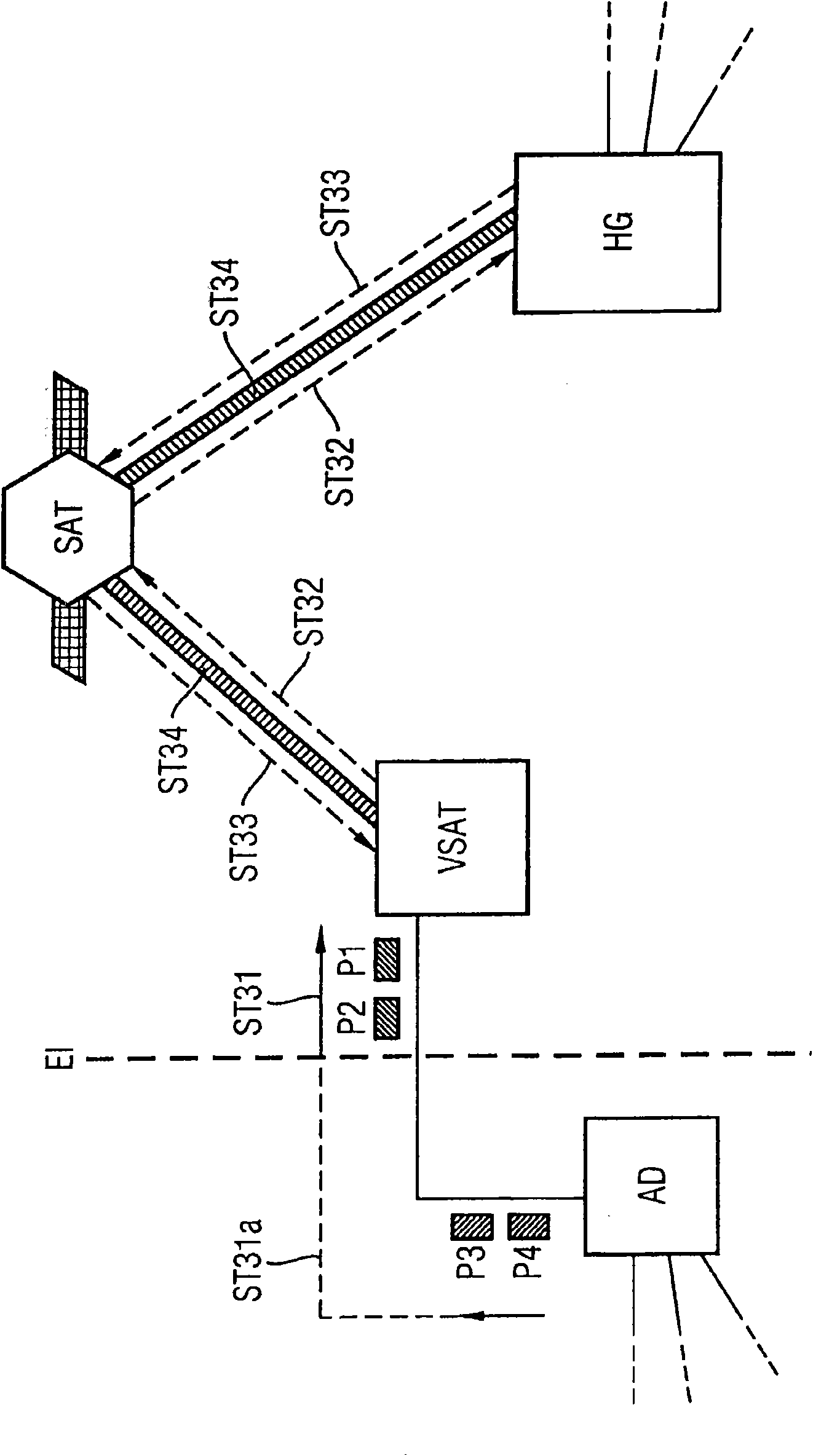
[0075] According to an embodiment of the present invention, in a satellite system where VoIP communication uses a dynamic rate-based allocation technique, an access device can communicate with a remote satellite terminal through a bandwidth control message. Such bandwidth control messages contain information to be used by the remote satellite terminal regarding bandwidth allocation requirements for one or more VoIP calls. The remote satellite terminal is able to recognize received message packets as control message packets and distinguish them from data / voice packets that must be transmitted over the satellite link. Once the bandwidth request is received by the remote satellite terminal, the remote satellite terminal analyzes the information contained in said message regarding the bandwidth allocation requirements for a given group of VoIP calls. If the analyzed information necessitates bandwidth allocation, th...


PUM


Abstract

A method and a system for allocating bandwidth for VoIP calls over a satellite communication system, in which a remote satellite terminal (VSAT) is requesting to a hub-gateway (HG), bandwidth to be allocated according to a dynamic technique based on the packet rate between an access device (AD) and the remote satellite terminal (VSAT), comprising: a) by the access device (AD), sending a smart IP packet (SP) to the remote satellite terminal (VSAT), having the function of a bandwidth control message packet, containing information on bandwidth allocation requirements for a given set of VoIP calls; b) by the remote satellite terminal (VSAT), identifying the received smart IP packet SP as the control message packet; c) by the remote satelli-te terminal (VSAT), analyzing the information on bandwidth allocation requirements contained in the received smart IP packet (SP); and d) by the remote satellite terminal (VSAT), upon necessity, requesting to the hub-gateway (HG) bandwidth to be allocated in accordance with the analyzed information on bandwidth allocation requirements.

Description

technical field [0001] The present invention generally relates to bandwidth allocation in VoIP telecommunication systems, wherein bandwidth is allocated according to dynamic rate based techniques. Background technique [0002] The invention is illustrated with a possible application of the invention in a satellite telecommunication system. [0003] Satellite communications are characterized by scarce and expensive bandwidth. The lack of satellite bandwidth requires bandwidth to be reused through a suitable centralized access method controlled by a Hub-gateway device. The main disadvantage of such a centralized bandwidth rate control method is that it implies round-trip satellite link delays for the bandwidth allocation to the remote stations to be done by the hub gateway, which is hereinafter schematically represented by FIGS. 1 to 5 is illustrated graphically. [0004] Fig. 1 is a block diagram schematically showing an exemplary architecture of a partially packet-based s...

Claims


Application Information

Patent Timeline
Patent Type & Authority Applications(China)
IPC IPC(8): H04B7/185
CPCH04B7/18582
Inventor C·E·巴普蒂斯塔W·卡多索
Owner SIEMENS AG
Learn More