Hull structure

A hull and stern technology, applied in the direction of hull, hull design, ship propulsion, etc., can solve the problems of low propulsion performance, inability to sufficiently reduce downflow, failure to achieve propulsion performance, etc., to improve propulsion performance and reduce viscous resistance. , the effect of flow field stabilization

Active Publication Date: 2009-12-30
SUMITOMO HEAVY IND MARINE & ENG
View PDF11 Cites 3 Cited by
  • Summary
  • Abstract
  • Description
  • Claims
  • Application Information

AI Technical Summary

Problems solved by technology

[0003] However, in the above-mentioned hull structure, sometimes the downflow generated around the stern cannot be sufficiently reduced, and the propulsion performance cannot be sufficiently improved.
Especially in the hull structure of a large ship, since the generation of this downdraft is remarkable, the propulsion performance is still low.

Method used


Image

  • Hull structure
  • Hull structure
  • Hull structure

Examples


Embodiment Construction

[0019] Hereinafter, preferred embodiments of the present invention will be described in detail with reference to the drawings. In addition, in the following description, "front", "rear", "left", "right", "upper", and "lower" correspond to the front-back direction, left-right (width) direction, and up-down direction of the hull, respectively.

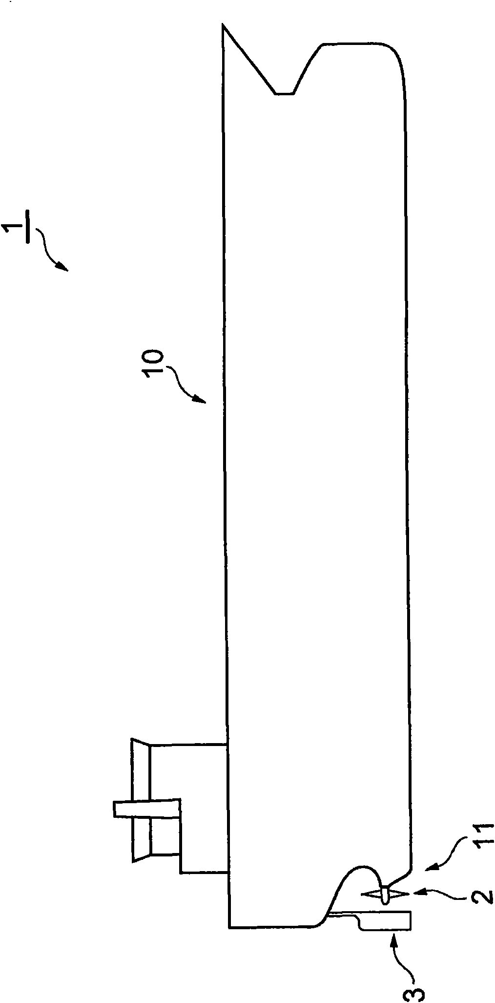
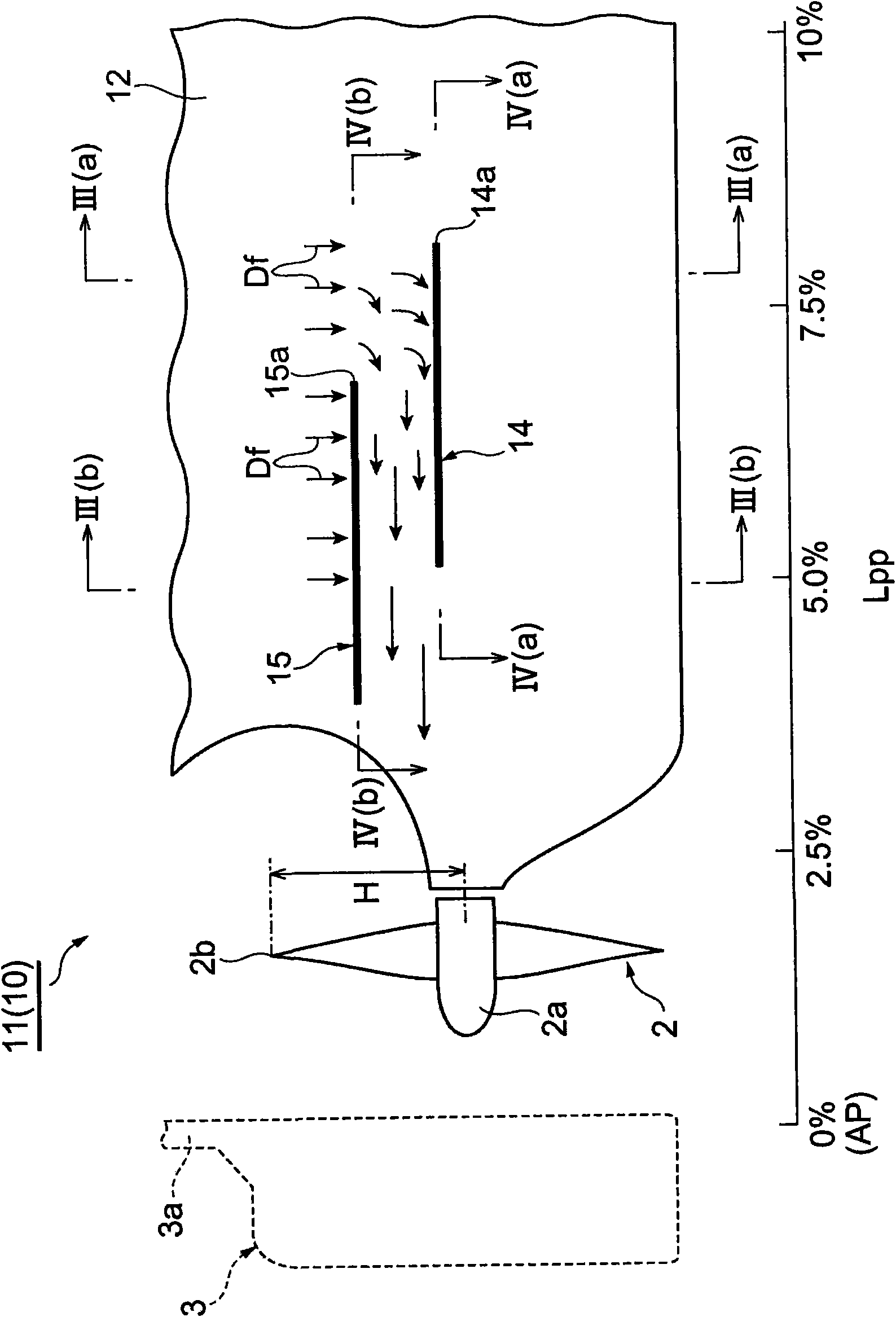
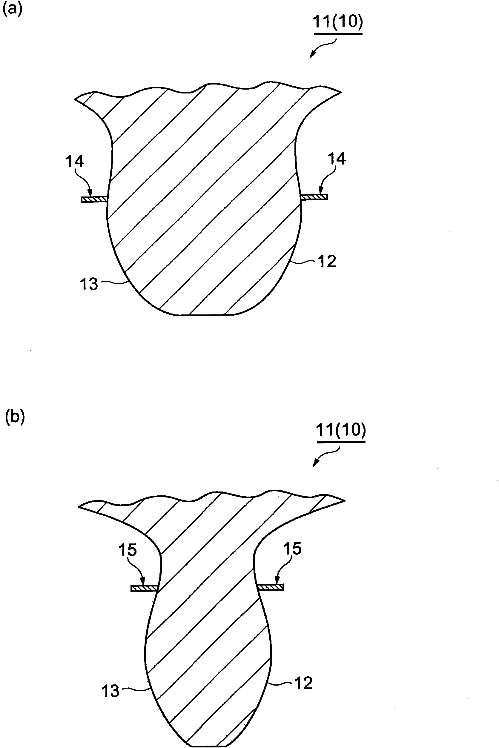
[0020] figure 1 It is a schematic side view showing the ship including the hull structure of the first embodiment of the present invention, figure 2 yes means figure 1 Enlarged side view of the stern portion of the ship, image 3 is along figure 2 Sectional view of line III-III, Figure 4 is along figure 2 Sectional drawing of the port side of the line IV-IV. Such as figure 1 , 2 As shown, the ship 1 of this embodiment is a large ship such as an oil tanker, and includes a hull 10 , propulsion propellers 2 and rudders 3 .

[0021] Such as image 3 As shown, the stern portion 11 of the hull 10 is a left-right symmetrical struc...


PUM


Abstract

The invention provides a hull structure capable of sufficiently improving pushing performance. A hull (10) has a first tail fin and a second tail fin (14, 15) respectively installed at right board hull side (12) and left board hull side in outwards extending manner. The first and the second tail fin (14, 15) are extended in horizontal direction, and installed between the after-perpendicular AP and the front position away from 10% of perpendicular length Lpp of the after-perpendicular AP. The first and the second tail fin (14, 15) can shade downward current and reduce downward current. The front end (14a) of the first tail fin (14) positioned below the second tail fin (15) is positioned in front of the front end (15a) of the second tail fin (15). Therefore, the current of the downward current Df controlled by the first tail fin (14) is guided between the first and the second tail fins (14, 15) so that the downward current Df is totally current to the back in horizontal direction and is accelerated.

Description

technical field [0001] The present invention relates to hull structures, and more particularly to hull structures of the stern portion of a hull. Background technique [0002] In the conventional hull structure, there may be a problem that a downflow accompanied by separation occurs in the water flow around the stern portion outside the hull, and the propulsion performance may be reduced due to the influence of the downflow. Therefore, as described in, for example, Japanese Patent Application Laid-Open No. 6-1281, a hull structure having a first skeg and a second skeg that are positioned on the starboard side and the port side, respectively, has been developed. Outer stick out setting. In such a hull structure, the first and second skegs having the same shape are positioned in the vicinity of the propulsion propeller at the stern, and are arranged vertically. Thereby, the flow of seawater around the stern portion can be straightened in the axial flow direction toward the p...

Claims


Application Information

Patent Timeline
Patent Type & Authority Applications(China)
IPC IPC(8): B63B1/32B63B1/26
CPCY02T70/12Y02T70/547Y02T70/10Y02T70/50B63B1/08B63B1/32B63H5/16
Inventor 高井通雄村上恭二青野健岩本三郎
Owner SUMITOMO HEAVY IND MARINE & ENG
Why Eureka
Try Eureka