Kitchen apparatus with ventilating device

A ventilation device and kitchen technology, applied in kitchen cabinets, household heating, lighting and heating equipment, etc., can solve the exhaust performance waste of remaining space, damage the convenience of the stove, the storage volume or the size of the blower in the left and right or front and rear directions Improve cooking operability by solving problems such as unit limitation

Inactive Publication Date: 2010-01-06
PANASONIC CORP
View PDF4 Cites 0 Cited by
  • Summary
  • Abstract
  • Description
  • Claims
  • Application Information

AI Technical Summary

Problems solved by technology

[0013] However, if the height of the top cover is simply lowered in the ways of Patent Documents 1, 3, and 4 for the purpose of increasing the exhaust gas collection performance, the front end of the top cover will be close to the front of the face during cooking operations, so There is a problem that there is a feeling of oppression, which impairs the convenience of using the stove
In addition, since the vertical length of the space from the upper surface of the top cover to the ceiling is necessarily increased, there is a problem of wasted extra space between the blower unit on the top cover and the ceiling, which has nothing to do with exhaust performance.
[0014] In addition, in any of the above-mentioned conventional examples, there is a problem that the storage volume or the size in the left-right or front-back directions of the article storage portion provided on the top cover is limited by the volume of the blower unit.

Method used


Image

  • Kitchen apparatus with ventilating device
  • Kitchen apparatus with ventilating device
  • Kitchen apparatus with ventilating device

Examples


no. 1 approach

[0085] Hereinafter, the present invention will be described based on the embodiments shown in the drawings.

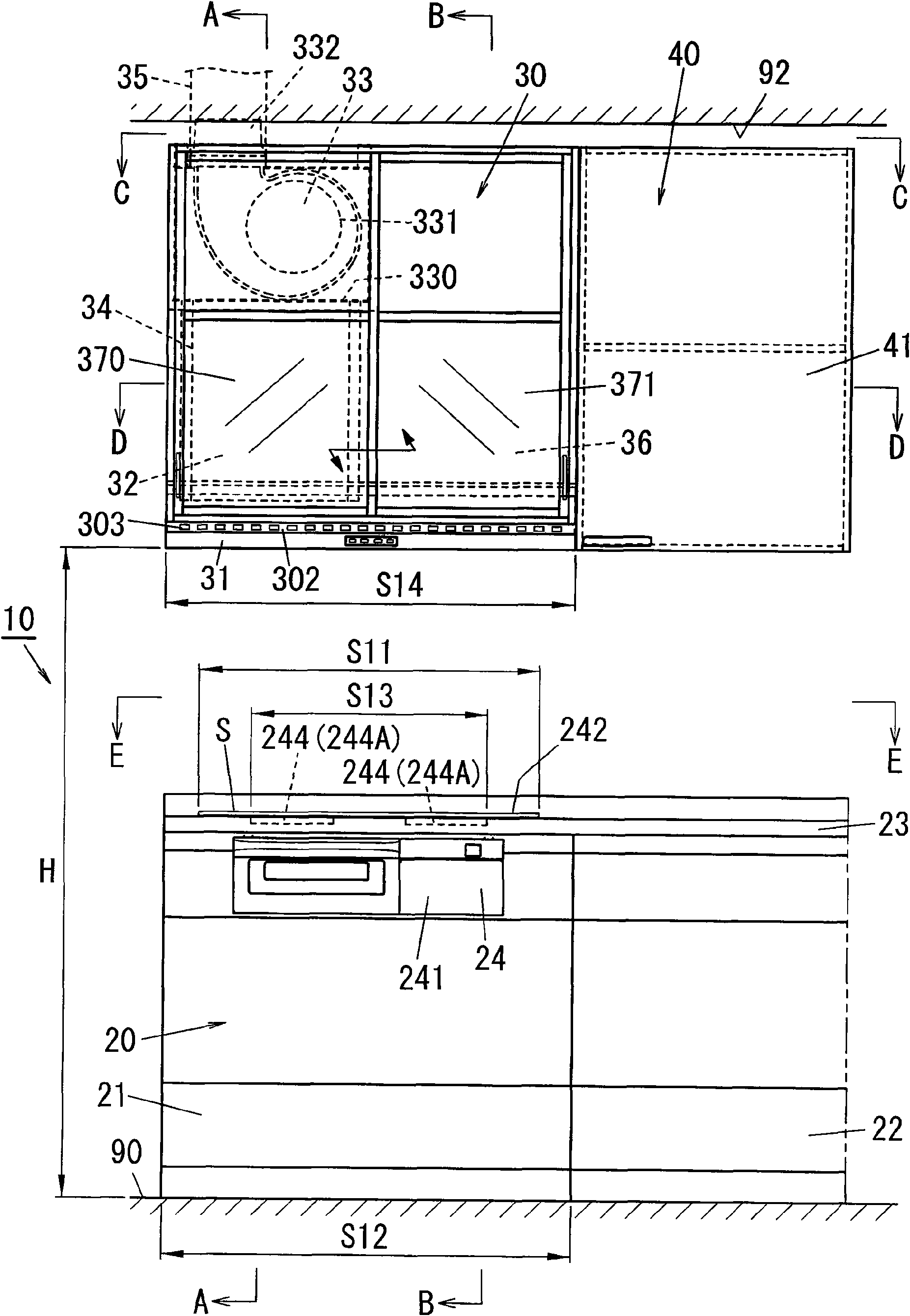
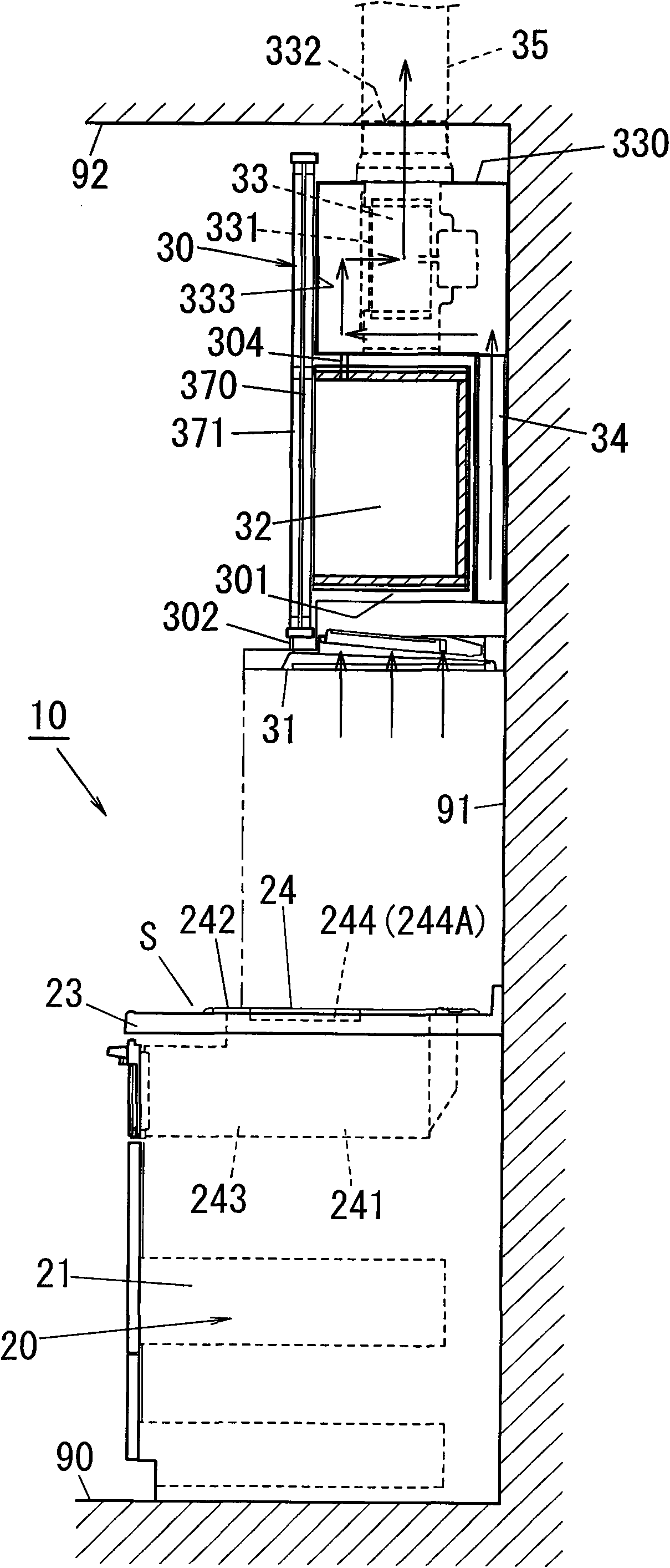
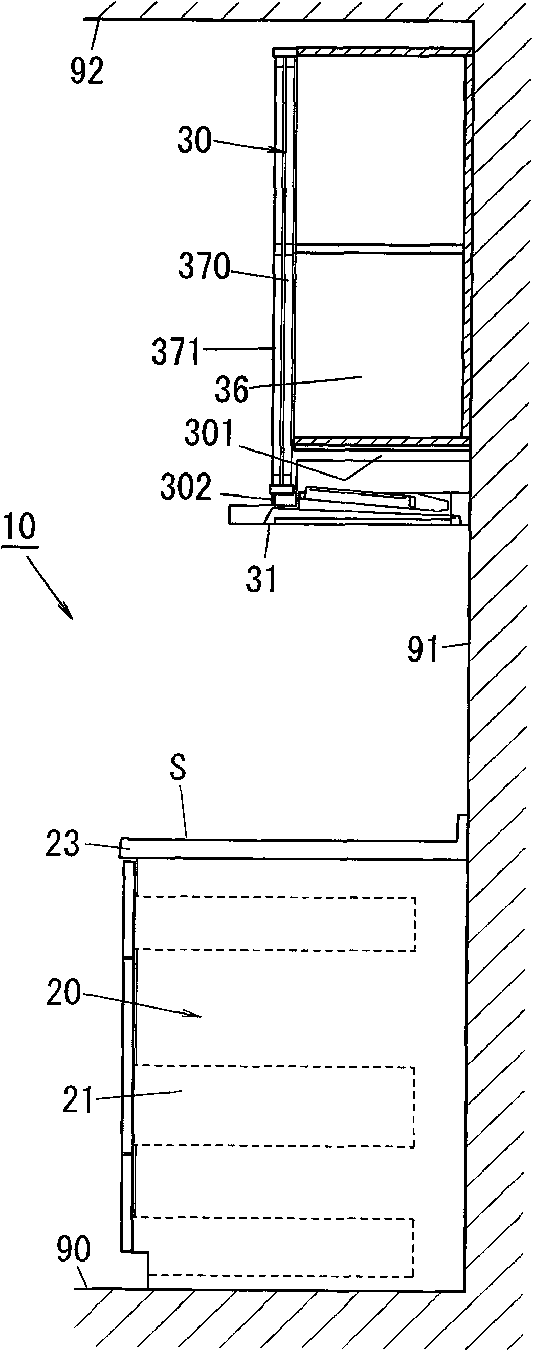
[0086] Figure 1 to Figure 6 In , the kitchen apparatus 10 with a ventilator which is 1st Embodiment of this invention is shown. The kitchen device 10 with a ventilator is configured such that a cooking table 20 , in which a stove 24 is embedded, is installed on a kitchen floor 90 , and a ventilator 30 is arranged above the stove 24 .

[0087] The cooking table 20 is configured by arranging a cooking table cabinet on the kitchen floor 90 , placing a platform 23 thereon, and inserting a stove 24 on the upper surface of the platform 23 . In addition, the ventilator 30 includes a top cover 31 and a blower unit 33 . On the side of the ventilation device 30 , a wall cabinet 40 is fixed on the wall surface 91 .

[0088]First, the cooking table 20 will be described in detail. In this embodiment, the cooking table cabinet is composed of the stove cabinet 21 provided below t...

no. 2 approach

[0141] Below, based on Figure 7 to Figure 12 A second embodiment of the present invention will be described.

[0142] The difference between the kitchen device 10 (10A) of this embodiment and the kitchen device 10 of the above-mentioned first embodiment is that the following structure is adopted: the top cover 31 (31A) on the stove 24 is extended to the side of the stove 24 In this way, the waste heat and exhaust gas of the desktop heating cooking machine 50 placed on the cooking table at the side of the stove 24 can also be collected and discharged. In addition, the description of the common parts with the first embodiment among the basic configurations will be omitted, and only the different configurations will be described.

[0143] On the side of the stove 24 on the upper surface of the cooking table 20A, a heater placement portion 231 in which a so-called table-top cooking machine (table-top cooking machine 50 ) can be placed is provided. The top cover 31A located abov...

no. 3 approach

[0163] Below, based on Figure 13 ~ Figure 15 , the third embodiment of the present invention will be described.

[0164] The kitchen device 10 ( 10B) of the present embodiment is different from the kitchen device 10A of the second embodiment described above in that the blower unit 33 ( 33B) is arranged in the ceiling. Further, detailed description of the basic configuration common to the second embodiment will be omitted, and only different configurations will be described.

[0165] In this embodiment, compared with the second embodiment, all or most of the blower unit 33B is located in the ceiling 92 (ceiling inner space 93), and the upper end of the top cover upper side article storage part 32 is set to reach the surface of the ceiling 92. Or reach a height close to the surface of the ceiling 92 .

[0166] That is to say, by using the top cover 31A integrally provided with the side extension top cover part 310, the top cover upper side article storage part 32 (32B) arrang...


PUM


Abstract

The present invention provides a kitchen apparatus (10) with a ventilating device, having a cooking bench (20) embedded with a kitchen range (24); a ventilating device (30) locating above the kitchen range (24) and having a top cap (31) and a blast blower unit (33). A front end section of the upper surface of the cooking bench (20) is provided with a kitchen range front operation region (S). the inner side of the kitchen range front operation region (S) is provided with the kitchen range (24). The top cap (31) is configured to cover a heater (244) of the kitchen range (24) from its vertical upper, and a front position of the top cap (31) is arranged between a front position of the kitchen range (24) and a front end of the heater (244) when downward looking.

Description

technical field [0001] The present invention relates to a kitchen device with a ventilator including a cooking table provided with a cooktop, and a ventilator arranged above the cooktop and having a top cover part and a blower part. Background technique [0002] Conventionally, there is known a kitchen device with a ventilator provided with a stove as a heater embedded in a cooking table, and a ventilator that collects exhaust gas such as oil fume and discharges it vertically above. This ventilator is constituted by arranging a top cover for collecting stove exhaust gas, and arranging a blower unit above the top cover. [0003] Most of the conventional stoves are configured by placing two heating elements embedded in the stove top in the left-right direction on the front side and one in the center back of the stove top in a triangular arrangement. The top cover which collects this stove exhaust gas is comprised so that the whole stove heating element may be covered. Theref...

Claims


Application Information

Patent Timeline
IPC IPC(8): A47B77/08F24C15/20
Inventor 木下敬介松下芳朗山田秀昭
Owner PANASONIC CORP
Why Eureka
Try Eureka