Panel body, space partition device, furniture with top board, and manufacturing method for panel body

A panel, one-sided technology, applied in the production of furniture cover, lamination device, furniture cover panel, etc., can solve the problem of inorganic matter and other problems of office workers, and achieve the effect of low cost

Inactive Publication Date: 2019-06-21
OKAMURA MFG CO LTD +2
View PDF15 Cites 0 Cited by
  • Summary
  • Abstract
  • Description
  • Claims
  • Application Information

AI Technical Summary

Problems solved by technology

However, since the base material is made of a rigid material, there is a problem of giving office workers an inorganic impression visually and tactilely.

Method used


Image

  • Panel body, space partition device, furniture with top board, and manufacturing method for panel body
  • Panel body, space partition device, furniture with top board, and manufacturing method for panel body
  • Panel body, space partition device, furniture with top board, and manufacturing method for panel body

Examples


no. 1 approach

[0083]

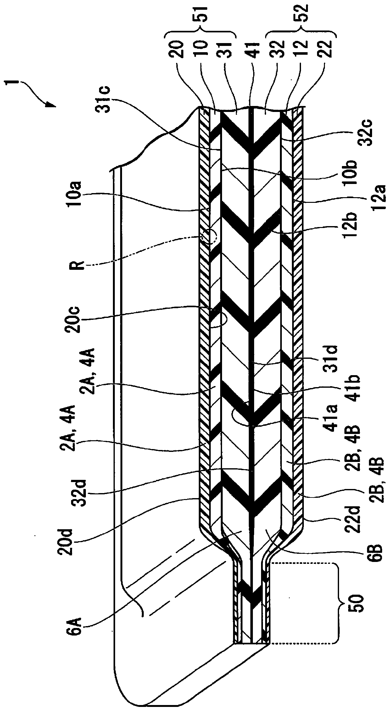
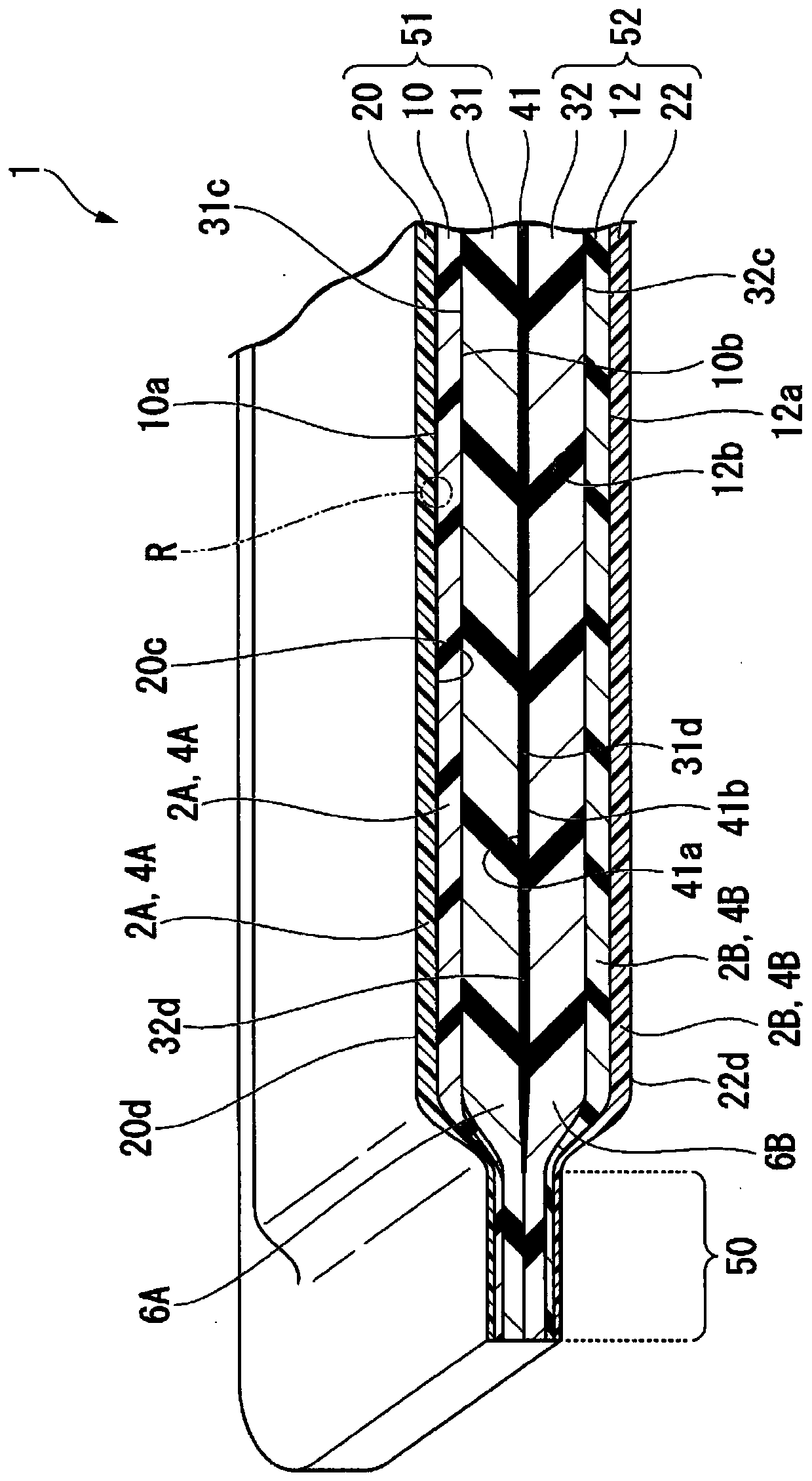
[0084] Such as Figure 1A , Figure 1B As shown, the panel body 1 of the first embodiment of the present invention is a panel body for dividing a space such as an office space not shown, and includes: a buffer layer (first buffer layer) including a fibrous base material 2A ) 51, a buffer layer (second buffer layer) 52, and a functional sheet 41 disposed between the buffer layers 51, 52 and having a predetermined function.

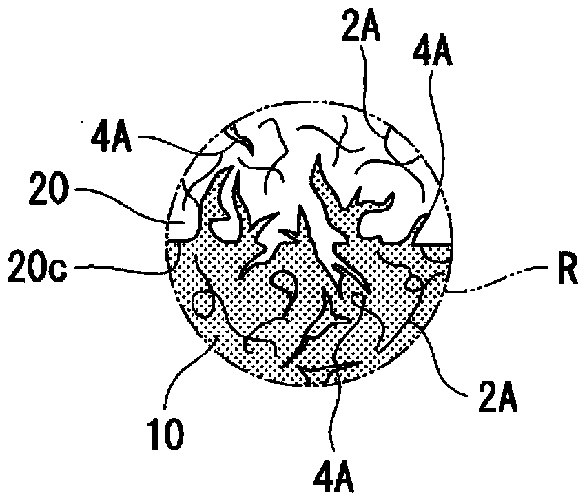
[0085] The buffer layer 51 includes: a thermal bonding layer 10 including a fibrous base material 2A and a bonding material 4A having a melting point lower than that of the base material 2A; a surface layer 20 bonded to a surface (one surface) 10a of the thermal bonding layer 10 It is composed of a base material 2A; and an intermediate layer 31 bonded to the back surface 10b of the thermally bonding layer 10 . The bonding material 4A is impregnated into the bonding surface 20 c of the surface layer 20 bonded to the thermal bonding layer 10 and t...

no. 2 approach

[0168] In the second embodiment, the same reference numerals are assigned to the same and similar components as those in the first embodiment, and detailed description thereof will be omitted.

[0169]

[0170] Such as Figure 8A , Figure 8B As shown, the panel body 1 of the second embodiment of the present invention is used to divide the space in the office space (not shown), and it includes: a buffer layer (laminate) 61 including a fibrous base material 2A, a buffer layer (laminate) body) 62, and the thermal bonding layer (first thermal bonding layer) 10 and thermal bonding layer (second thermal bonding layer) 12 disposed between these laminated bodies 61, 62, wherein the thermal bonding layer (first thermal bonding layer) The thermal bonding layer) 10 includes a fibrous base material 2A and a bonding material 4A having a melting point lower than that of the base material 2A; Low bonding material 4B. Surface layer 20 made of base material 2A is bonded to surface (one s...


PUM

PropertyMeasurementUnit
melting pointaaaaaaaaaa

Abstract

A panel body (1) has a cushion layer (51) containing a fibrous substrate (2A) and a cushion layer (52) containing a fibrous substrate (2B), wherein the first cushion layer (51) and the second cushionlayer (52) each have: a thermal coupling layer (10, 12) that includes the substrate (2A, 2B) and a bonding material with a lower melting point than the substrate (2A, 2B); and a surface layer (20, 22)that is attached to one face of the thermal coupling layer (10, 12) and is constituted by the substrate (2A, 2B).

Description

technical field [0001] The invention relates to a panel body, a partition device, a daily article with a top plate, and a manufacturing method of the panel body. [0002] This application is based on the patent application No. 2016-217664 filed in Japan on November 7, 2016, the patent application No. 2017-017854 filed in Japan on February 2, 2017, and the patent application 2017 filed in Japan on February 2, 2017 -017855 claims priority, the contents of which are hereby incorporated by reference. Background technique [0003] In general, in office spaces such as offices and public facilities, daily necessities with ceilings are arranged in order to provide office workers with a space to perform work. In such an office space, in order to provide an environment that divides the work space on the ceiling from the outside space and blocks the office worker's line of sight so that the office worker can concentrate, sometimes a panel body, A partition device including a panel bo...

Claims


Application Information

Patent Timeline
Patent Type & Authority Applications(China)
IPC IPC(8): E04B2/74A47B17/00A47B96/20
CPCA47B17/00A47B96/20B32B3/06B32B3/08B32B3/12B32B3/263B32B5/022B32B5/024B32B5/14B32B5/18B32B5/245B32B5/26B32B7/02B32B7/12B32B25/042B32B25/045B32B25/08B32B25/10B32B27/065B32B27/12B32B27/32B32B27/34B32B27/36B32B27/40B32B2260/023B32B2260/046B32B2262/02B32B2262/0253B32B2262/0261B32B2262/0269B32B2262/0276B32B2262/101B32B2262/106B32B2266/0214B32B2307/102B32B2307/208B32B2307/21B32B2307/3065B32B2307/4026B32B2307/7145B32B2307/724B32B2307/7265B32B2479/00B32B2607/00E04B2/7405A47B97/00A47B2200/12B32B27/08B32B37/06B32B37/182B68G7/02B68G13/00
Inventor 山本崇之马场信彦冈村英治塚本隆宏崎本隆之
Owner OKAMURA MFG CO LTD
Why Eureka
Try Eureka