Expanding hydraulic anchor

A hydraulic anchor and expansion type technology, applied in wellbore/well components, earthwork drilling, etc., can solve the problems of oil well engineering accidents, anchor claw stuck pipe string, unable to carry out oil well operations, etc., to achieve reliable work and avoid engineering effect of accident

Inactive Publication Date: 2010-01-06
东营市兆鑫工贸有限责任公司
View PDF0 Cites 2 Cited by
  • Summary
  • Abstract
  • Description
  • Claims
  • Application Information

AI Technical Summary

Problems solved by technology

However, the existing hydraulic anchors are anchored by flukes, and the flukes protrude out of the anchor pipe string by the pressure difference between the two ends of the flukes. Due to the sealing requirements between the flukes and the body, the flutes are cylindrical, and the flutes and the main body are required to be sealed. The installation gap between the main bodies is very small. After long-term work in the well, due to corrosion, scaling, sand settling and other reasons, the anchor claws are not easy to retract, causing the anchor claws to get stuck in the pipe string, so that the pipe string in the well cannot be lifted out, and oil well operations cannot be carried out. Causing engineering accidents in oil wells

Method used


Image

  • Expanding hydraulic anchor
  • Expanding hydraulic anchor

Examples


Embodiment Construction

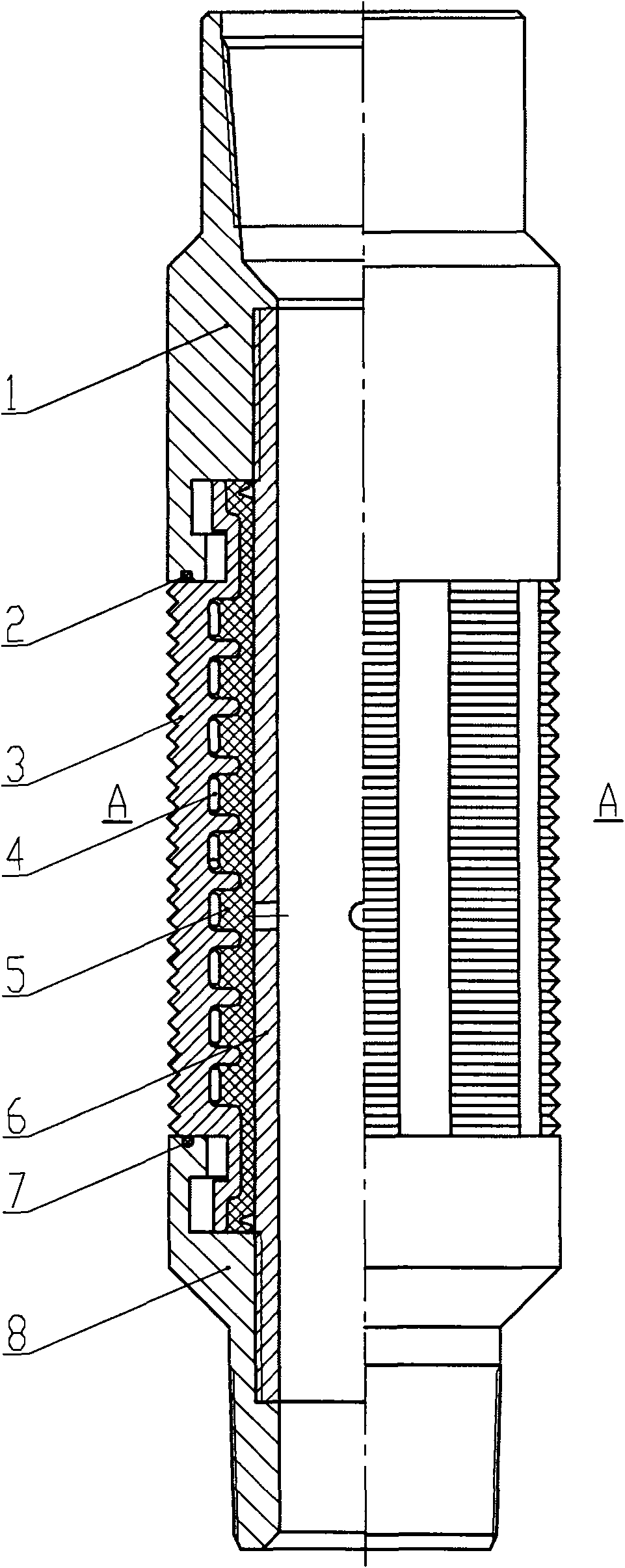
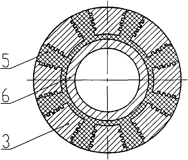
[0010] Attached below figure 1 , 2 Examples of the present invention will be described.

[0011] It is composed of upper joint 1, upper sand ring 2, anchor claw 3, hoop spring 4, rubber tube 5, inner tube 6, lower sand ring 7, and lower joint 8. The anchor claw 3 is embedded in the rubber tube 5 in strip shape. In the longitudinal groove, there are transverse teeth on the outer side of the anchor claw 3, which are used for anchoring the casing, and there are radial grooves on the inner side of the anchor claw 3, and there is a hoop spring 4 in the radial groove, and the hoop spring 4 encloses the rubber tube 5, Anchor fluke 3, hoop spring 4, and rubber tube 5 are vulcanized into one body and set outside the inner tube 6. The upper part of the inner tube 6 is connected with the upper joint 1, the lower part of the inner tube 6 is connected with the lower joint 8, and the lower part of the upper joint 1 buckles the anchor fluke 3 The upper part makes the fluke 3 tops not fall ...


PUM


Abstract

The invention relates to an expanding hydraulic anchor, comprising an upper joint, an anchor claw, a hoop spring, a rubber barrel, an inner pipe and a lower joint, wherein, the anchoring claw is embedded in the vertical groove of the rubber barrel in the form of a strip; transverse cogwheels are arranged outside the anchor claw and a radial groove is arranged inside the anchor jaw; the hoop spring is arranged in the radial groove; the hoop spring covers the rubber barrel; the anchor claw, the hoop spring and the rubber barrel are vulcanized and integrated to be sleeved outside the inner pipe; the upper part of the inner pipe is connected with the upper joint; the lower part of the inner pipe is connected with the lower joint; the lower part of the upper joint is buckled with the upper part of the anchor jaw; and the upper part of the lower joint is buckled with the lower part of the anchor jaw. Pressure is transmitted inside to result in the expansion of the rubber barrel; the anchor is pushed out and anchored on an oil well sleeve; when requiring no anchor, the oil pressure is balanced, the rubber barrel is retracted under the actions of the hoop spring and the elasticity thereof; and the anchor jaw is expanded with the rubber barrel without clearance fits of metals; therefore, the anchor jaw can work freely, and can be anchored and retracted; the work is reliable without blocking pipe columns; and the engineering accidents of the oil well can be prevented.

Description

1. Technical field [0001] The invention belongs to a pipe column anchoring device used in an oil production well in an oil field, and is an expansion type hydraulic anchor. 2. Background technology [0002] When the oil well is pumped, the load of the fluid column on the tubing and the sucker rod is transferred alternately with the up and down strokes of the pumping unit, which makes the tubing stretch and shorten, resulting in low efficiency of the pump, and the tubing trips and falls into the well. In order to avoid the above problems, hydraulic anchors were used on site to fix the tubing and prevent the tubing from stretching. During the construction of some oil-water wells, in order to prevent damage to downhole tools such as packers caused by pipe string movement, hydraulic anchors are also connected to the tools. However, the existing hydraulic anchors are anchored by flukes, and the flukes protrude out of the anchor pipe string by the pressure difference between the ...

Claims


Application Information

Patent Timeline
Patent Type & Authority Applications(China)
IPC IPC(8): E21B23/01
Inventor 曲绍琨王中华马宝龙
Owner 东营市兆鑫工贸有限责任公司
Why Eureka
Try Eureka