Ejector rod of injection mold

A technology for injection molds and ejector pins, which is applied in the field of injection molds and can solve problems such as unsatisfactory, increased friction resistance of template holes, and large friction resistance.

Active Publication Date: 2021-12-24
NINGBO DOOYA MECHANIC & ELECTRONICS TECH
View PDF7 Cites 0 Cited by
  • Summary
  • Abstract
  • Description
  • Claims
  • Application Information

AI Technical Summary

Problems solved by technology

The ejector pin in the prior art still has the following disadvantages: impurities such as metal particles in the external environment or mold friction and wear are easily attached to the outer peripheral surface of the ejector pin, which increases the frictional resistance of the ejector pin and the template hole of the injection mold matched with it , the sliding is not smooth, and the ejector pin structure in the prior art still cannot meet the needs of lubrication well, the lubricating surface is small and the lubrication effect is still unsatisfactory, the friction resistance of the ejector pin and the template hole of the injection mold matched with it is relatively large, The sliding is not smooth, and the ejector pin of the injection mold is prone to jamming, bending or breaking, etc.

Method used


Image

  • Ejector rod of injection mold
  • Ejector rod of injection mold
  • Ejector rod of injection mold

Examples


Embodiment Construction

[0026] The specific embodiments of the present invention will be further described below in conjunction with the accompanying drawings. What needs to be declared here is that the descriptions of these specific implementations are used to help understand the present invention, but are not intended to limit the present invention. In addition, the technical features involved in the various specific embodiments of the present invention described below may be combined with each other as long as they do not constitute conflicts with each other.

[0027] Such as figure 1 , figure 2 , image 3 , Figure 4 , Figure 5 , Figure 6 , Figure 7 , Figure 8 shown.

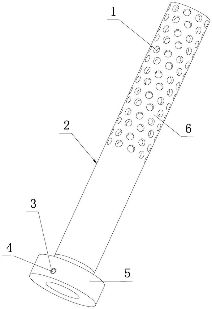
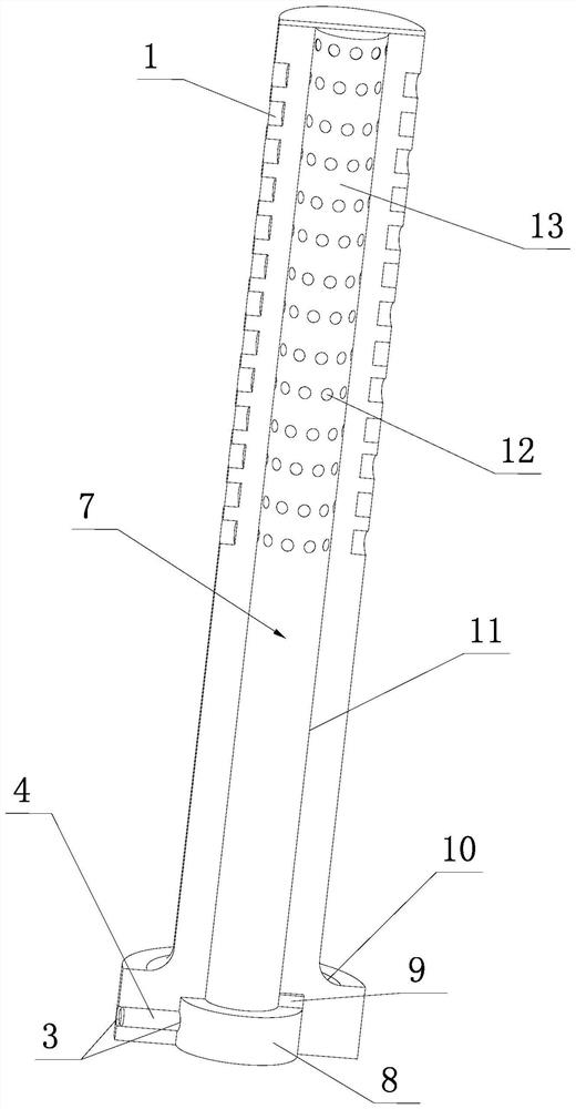
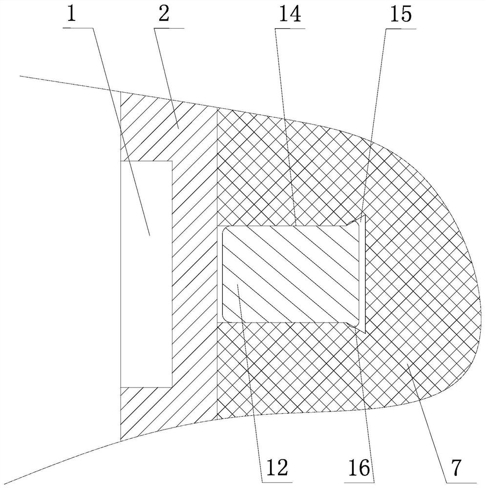
[0028] A ejector pin of an injection mold according to the present invention includes a cylindrical ejector body 2 made of mold steel, and a first shoulder 5, which is coaxially connected with the cylindrical ejector body 2, generally It is integrally formed as a whole, and a concave arc-shaped transition surface 10 i...


PUM


Abstract

The invention discloses an ejector rod of an injection mold. The ejector rod comprises a cylindrical ejector rod body made of mold steel, multiple first round pits are formed in the outer circumferential surface of the ejector rod body in sliding fit with a mold plate hole of the injection mold, and lubricating grease is arranged in each first round pit; a round center hole is formed in the ejector rod body, a round rod made of a non-magnetic material is sleeved with the center hole, and multiple cylindrical magnetic blocks which are in one-to-one correspondence with the first round pits and are used for adsorbing metal particles generated in production to the inner walls of the first pits are arranged on the outer circumferential surface of the round rod; the multiple first pits are arranged in rows and columns on the outer circumferential surface of the ejector rod body, and the distance between every two adjacent first round pits in the upper row is smaller than the diameter of the first round pit in the lower row. According to the ejector rod, the phenomenon that the metal particles generated in the injection molding process are attached to the outer circumferential surface of the ejector rod is greatly reduced, the lubricating effect between the matched parts of the ejector rod and the mold plate hole is good, and sliding is smooth.

Description

technical field [0001] The invention relates to the technical field of injection molds, in particular to a ejector pin of an injection mold. Background technique [0002] Injection molding is widely used in the production and manufacture of plastic products due to its advantages of high efficiency and high quality. Injection mold is the direct carrier for the production of plastic products. Compared with other mechanical equipment, most parts of injection mold have relatively small wear loss, can run for a long time, and have fewer failures. However, pins such as the ejector pin of the injection mold are easily stuck, bent or broken, so that the ejection work cannot be successfully completed, which affects the normal progress of the entire production process. In the injection molding process, the failure of the ejector pin accounts for most of the mold failures, that is, the failure of the ejector pin has become the main source of mold failure in the current injection moldi...

Claims


Application Information

Patent Timeline
Patent Type & Authority Applications(China)
IPC IPC(8): B29C45/40
CPCB29C45/401
Inventor 许少锋高海江吴楠金超王宗宝
Owner NINGBO DOOYA MECHANIC & ELECTRONICS TECH
Why Eureka
Try Eureka