Multifrequency antenna

一种多频天线、交界线的技术,应用在天线、隙缝天线、电气短天线等方向,能够解决无法满足高传输速率、天线频带衰减等问题,达到减少设计面积、降低成本的效果

Inactive Publication Date: 2010-01-06
HONG FU JIN PRECISION IND (SHENZHEN) CO LTD +1
View PDF0 Cites 3 Cited by
  • Summary
  • Abstract
  • Description
  • Claims
  • Application Information

AI Technical Summary

Problems solved by technology

In the design process of the microstrip antenna, the reduction of the antenna size usually leads to the attenuation of the antenna frequency band, which cannot meet the needs of high-speed wireless communication.

Method used


Image

  • Multifrequency antenna
  • Multifrequency antenna
  • Multifrequency antenna

Examples


Embodiment Construction

[0010] The embodiments of the present invention will be further described in detail below in conjunction with the accompanying drawings.

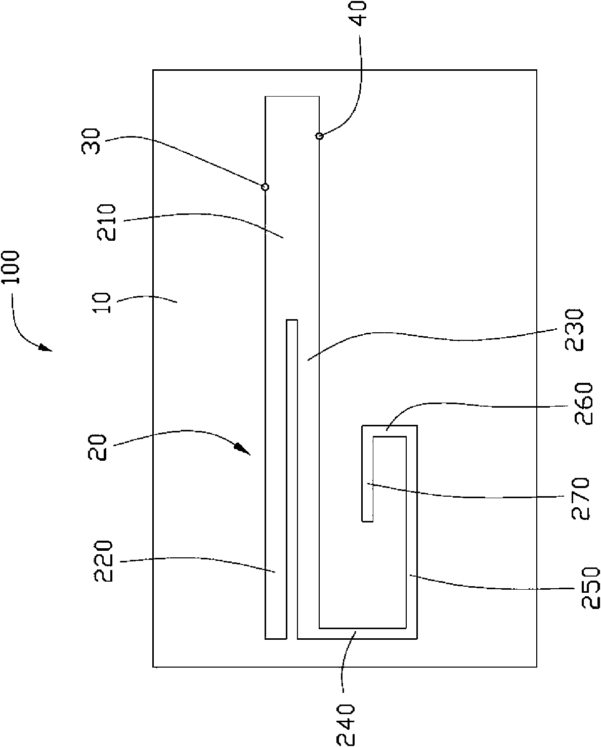
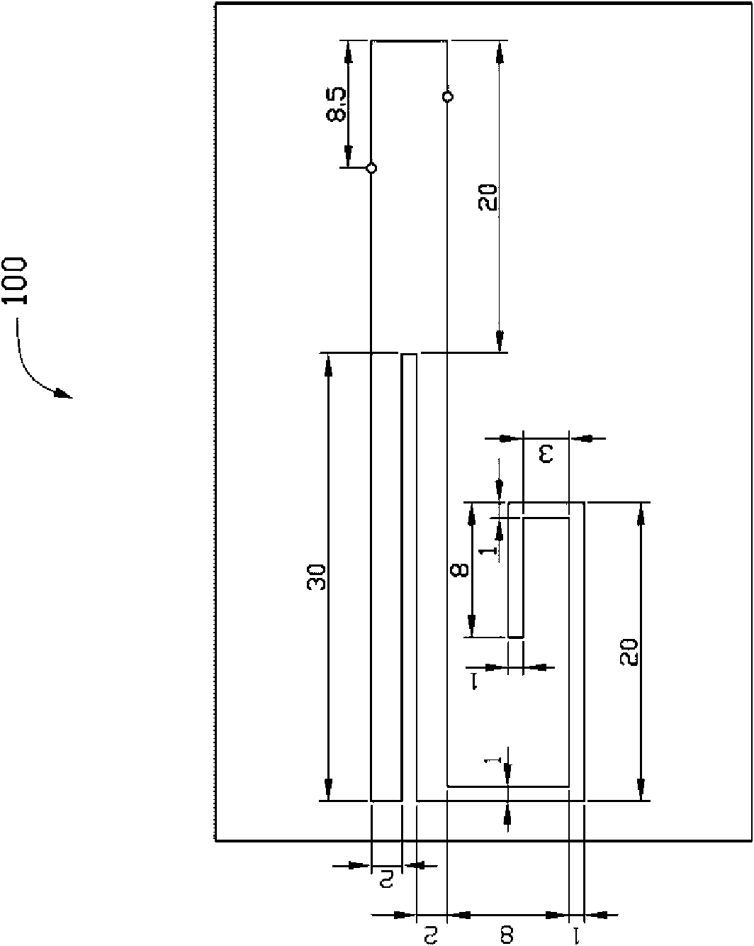
[0011] see figure 1 and figure 2 , is a multi-band antenna 100 provided in an embodiment of the present invention. The multi-frequency antenna 100 includes a metal surface 10 having an unclosed slot structure 20 , a feeding point 30 and a grounding portion 40 .

[0012] The metal surface 10 can be the surface of a metal sheet, or the metal surface of a printed circuit board.

[0013] The slot structure 20 can be formed on the metal surface 10 by stamping. At this time, the metal surface 10 is the surface of a metal sheet, or it can be formed on the metal surface 10 by etching. When, the metal surface 10 is a metal surface of a printed circuit board. The slot structure 20 includes a first rectangular slot 210, a second rectangular slot 220, a third rectangular slot 230, a fourth rectangular slot 240, a fifth rectangular slot 250, a sixt...


PUM


Abstract

The invention relates to a multifrequency antenna, comprising a metal surface, wherein, the metal surface is provided with an unclosed slotted hole structure, a feed point and an ground connection part. The slotted hole structure comprises a first rectangular slotted hole, a second rectangular slotted hole, a third rectangular slotted hole, a fourth rectangular slotted hole, a fifth rectangular slotted hole, a sixth rectangular slotted hole and a seventh rectangular slotted hole, and the second rectangular slotted hole and the third rectangular slotted hole are extended from the same side of the first rectangular slotted hole and are arranged in parallel with each other; and extending outside from one side of the third rectangular slotted hole away from the first rectangular slotted hole, the fourth rectangular slotted hole, the fifth rectangular slotted hole, the sixth rectangular slotted hole and the seventh rectangular slotted hole are sequentially and vertically connected end to end and are bent and folded inwards. The feed point is positioned on the boundary of the first rectangular slotted hole and the metal surface. By arranging the slotted hole structure formed by a plurality of rectangular slotted holes on the same metal surface, the multifrequency antenna of the invention can realize the purpose that one slotted hole antenna can adapt to two different ranges of working frequency, thereby effectively reducing the design area of the antenna and lowering the cost.

Description

technical field [0001] The invention relates to an antenna. Background technique [0002] In recent years, with the advancement of wireless communication technology and the close integration with international networks, wireless communication applications have shown explosive growth. In current daily life, wireless communication related products can be seen everywhere, for example, mobile phone (mobile phone), global positioning system (global positioning system, GPS), wireless fidelity (Wireless Fidelity), wireless local-area network (wireless local-area network, WLAN), bluetooth (bluetooth) products, notebook computers with wireless communication functions, etc. [0003] And all wireless communication systems are indispensable for antennas. Antennas are the gateway to wireless communication systems and the quality of antenna design will directly affect the communication quality of products. In different areas of the world, the wireless communication standards set are dif...

Claims


Application Information

Patent Timeline
Patent Type & Authority Applications(China)
IPC IPC(8): H01Q1/36H01Q13/10H01Q5/00
CPCH01Q13/10H01Q1/243H01Q9/0421H01Q5/0058H01Q5/371
Inventor 姜礼城杨志渊柯宏昌郭柏伟苏硕彬陈文俊
Owner HONG FU JIN PRECISION IND (SHENZHEN) CO LTD
Why Eureka
Try Eureka