Eureka AIR delivers breakthrough ideas for toughest innovation challenges, trusted by R&D personnel around the world.

Slot array antenna for vehicle radar

A technology of slot array antenna and vehicle radar, which is applied in the field of slot array antenna, can solve problems such as inability to match impedance, and achieve the effect of preventing reflected waves and preventing reflection

Inactive Publication Date: 2016-02-10
HYUNDAI MOTOR CO LTD
View PDF1 Cites 10 Cited by
  • Summary
  • Abstract
  • Description
  • Claims
  • Application Information

AI Technical Summary

Problems solved by technology

[0006] Since the conventional waveguide slot array planar antenna does not have a structure for realizing the impedance matching of the antenna, therefore, the impedance matching may not be possible

Method used


Image

  • Slot array antenna for vehicle radar
  • Slot array antenna for vehicle radar
  • Slot array antenna for vehicle radar

Examples


Embodiment Construction

[0024] The above objects, features and advantages will become more apparent through the following detailed description with reference to the accompanying drawings, so that those skilled in the art can understand the technical spirit of the present invention. Further, in the following description of the present invention, if it is determined that a detailed description of known techniques related to the present invention unnecessarily obscures the gist of the present invention, the description will be omitted. Hereinafter, exemplary embodiments of the present invention will be described in detail with reference to the accompanying drawings.

[0025] The terms used herein are for describing particular embodiments only and are not intended to limit the present invention. The singular forms used herein are intended to also include the plural unless the context clearly dictates otherwise. It is also to be understood that when used in this specification, the term "comprises" specif...


PUM


Abstract

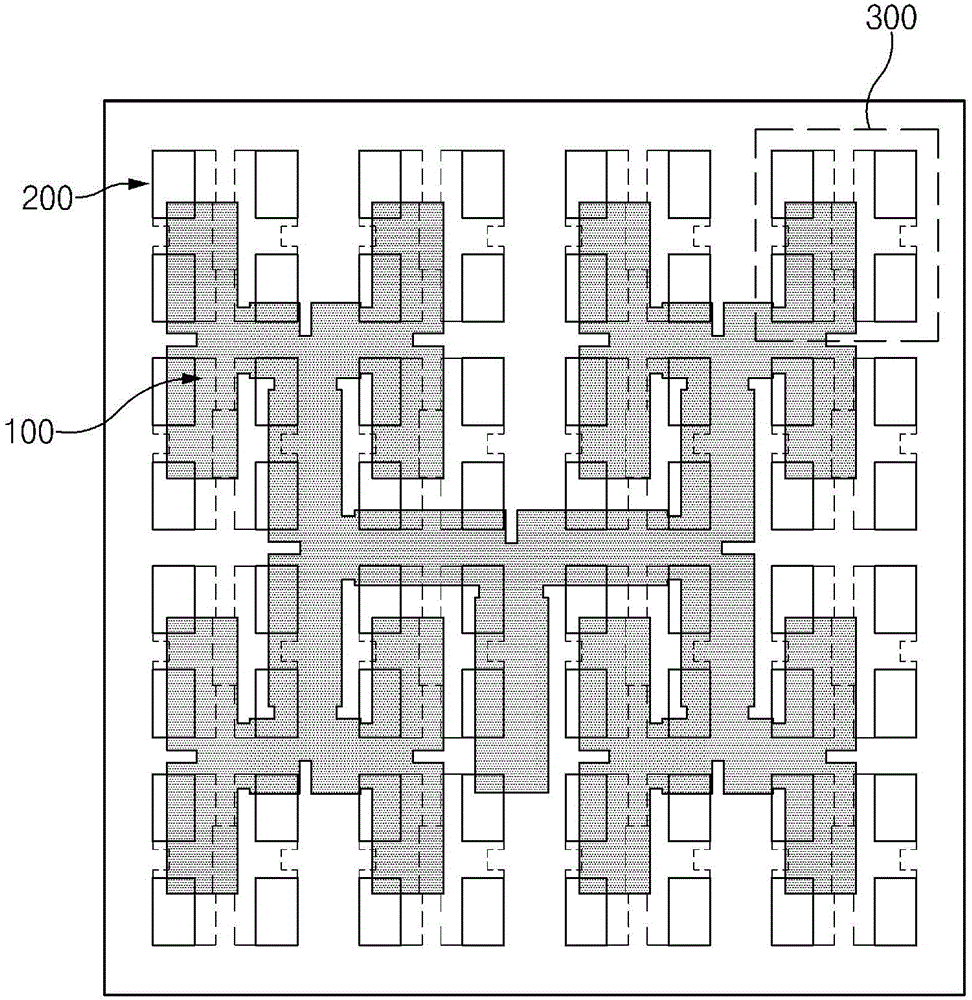
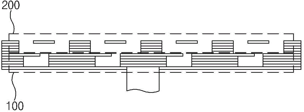
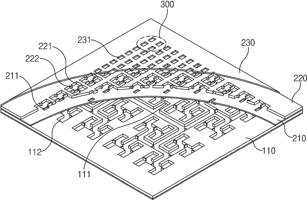
A slot array antenna for a vehicle radar system is provided. The antenna includes a cavity which separates a magnetic field signal applied through a feeding waveguide while maintaining phase and amplitude and which radiates such signals to the each radiating slot. A slot array antenna includes a 2-by-2 unit cell arrangement and a feeding plate member that forms a feeding waveguide. In addition, a first slot plate member includes a coupling slot, a cavity plate member forms a cavity, and a second slot plate member has a plurality of sequentially laminated radiation slots. Further, the cavity includes a partition wall for impedance matching.

Description

[0001] Cross References to Related Applications [0002] Pursuant to 35 U.S.C. §119(a), this application claims the benefit of Korean Application No. 10-2014-0098402 filed July 31, 2014, the entire contents of which are incorporated herein. technical field [0003] The present invention relates to a slot array antenna for a vehicular radar system, and more particularly, to a slot array antenna for a vehicular radar system comprising a layered structure, due to the repeated structure of a plurality of unit cells, the The slot array antenna has increased design freedom and is also ultra-thin, lightweight, has low-loss characteristics, and also has broadband characteristics due to the broadband feed structure. Background technique [0004] Vehicle radar systems are generally mounted on the front of the vehicle, and are required to be thin and lightweight. Since higher frequency signals (eg, signals exceeding tens of GHz) are usually transmitted and received at constant field s...

Claims


Application Information

Patent Timeline
Patent Type & Authority Applications(China)
IPC IPC(8): H01Q13/10H01Q21/00H01Q1/32H01Q1/36
CPCG01S13/931H01Q1/3233H01Q13/18H01Q21/0037H01Q21/064
Inventor 金东真
Owner HYUNDAI MOTOR CO LTD
Why Eureka
Eureka Blog
Learn More