Wavelength multiplexed optical system with multimode optical fibers

一种光学系统、多路复用的技术,应用在光纤传输领域,能够解决没有提及波长多路复用等问题

Active Publication Date: 2010-01-06
DRAKA COMTEQ BV
View PDF9 Cites 8 Cited by
  • Summary
  • Abstract
  • Description
  • Claims
  • Application Information

AI Technical Summary

Problems solved by technology

However, the document does not mention wavelength multiplexing

Method used


Image

  • Wavelength multiplexed optical system with multimode optical fibers
  • Wavelength multiplexed optical system with multimode optical fibers
  • Wavelength multiplexed optical system with multimode optical fibers

Examples


Embodiment Construction

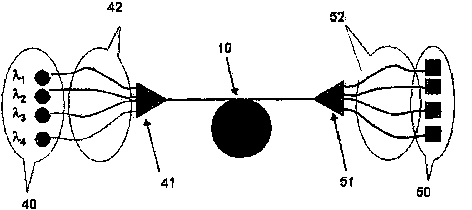
[0053] The present invention proposes an optical system that allows the transmission of wavelength multiplexed multimode signals to increase the bit rate of multimode communication networks beyond 10GbE. This increased bit rate is achieved without adversely affecting bandwidth. In fact, this system according to the invention proposes to compensate for the modal dispersion upstream of each multiplexed channel within the multiplexer so that the signal received at the output of the multimode transmission fiber has a minimum Modal dispersion. This transmission system can ensure that a bandwidth greater than or equal to 2000MHz-km (respectively 4700MHz-km) can be obtained after propagation over 300m (respectively 550m) on the multimode optical fiber.

[0054] figure 1 An optical system according to the invention is schematically shown. figure 1 The system is a WDM wavelength multiplexing multimode optical transmission system.

[0055] figure 1 Multiple light sources 40 are sho...


PUM


Abstract

An optical system comprises a multimode optical fibre (10) capable of transmitting wavelength multiplexed optical signals and a plurality of multimode modal dispersion compensation optical fibres (42). Each modal dispersion compensation fibre (42) is capable of transmitting one of the wavelengths of the multiplex and each compensation fibre (42) has an optimized index profile such that the modal dispersion for the transmitted wavelength is inversely equal to the modal dispersion induced in the transmission fibre (10) for said wavelength. The system of the invention allows an increased bitrate without reducing the bandwidth.

Description

technical field [0001] The present invention relates to the field of optical fiber transmission, and more particularly to multimode optical fibers used in short-distance optical transmission systems requiring large bandwidth. Background technique [0002] Multimode fiber is used for short distance applications and local area networks. The core of a multimode fiber typically has a diameter of about 50 μm, compared to a core diameter of about 8-9 μm for a single-mode fiber. Thus for a specific wavelength, multiple optical modes carrying the same information can propagate along the fiber simultaneously. Bandwidth is directly related to the group velocity of the optical modes propagating within the fiber's multimode core. To ensure high bandwidth, all modes need to have equal group velocities, in other words, intermodal dispersion, the difference in group velocities between lower and higher modes, should be zero, or at least minimized for certain wavelengths. Multimode fiber ...

Claims


Application Information

Patent Timeline
Patent Type & Authority Applications(China)
IPC IPC(8): H04J14/02H04B10/18H04B10/2581
CPCH04J14/0279H04J14/02H04B10/2581
Inventor Y·吕米诺D·莫兰A·戈拉米
Owner DRAKA COMTEQ BV
Why Eureka
Try Eureka