Probe card corrector

A technology for calibrating equipment and probe cards, applied to measuring devices, instruments, and optical devices, etc., can solve problems such as labor and time consumption, poor calibration accuracy, and inconvenience in use.

Inactive Publication Date: 2010-01-20
KING YUAN ELECTRONICS
View PDF0 Cites 6 Cited by
  • Summary
  • Abstract
  • Description
  • Claims
  • Application Information

AI Technical Summary

Problems solved by technology

Therefore, the user usually needs to calibrate the probe card between the two sets of equipment, which is not only inconvenient to use, but also consumes manpower and time, and the adjusted probe card may also cause positioning problems due to back and forth transportation and installation. The accuracy of the adjustment is deteriorated due to the offset, which leads to many problems

Method used


Image

  • Probe card corrector
  • Probe card corrector
  • Probe card corrector

Examples


Embodiment Construction

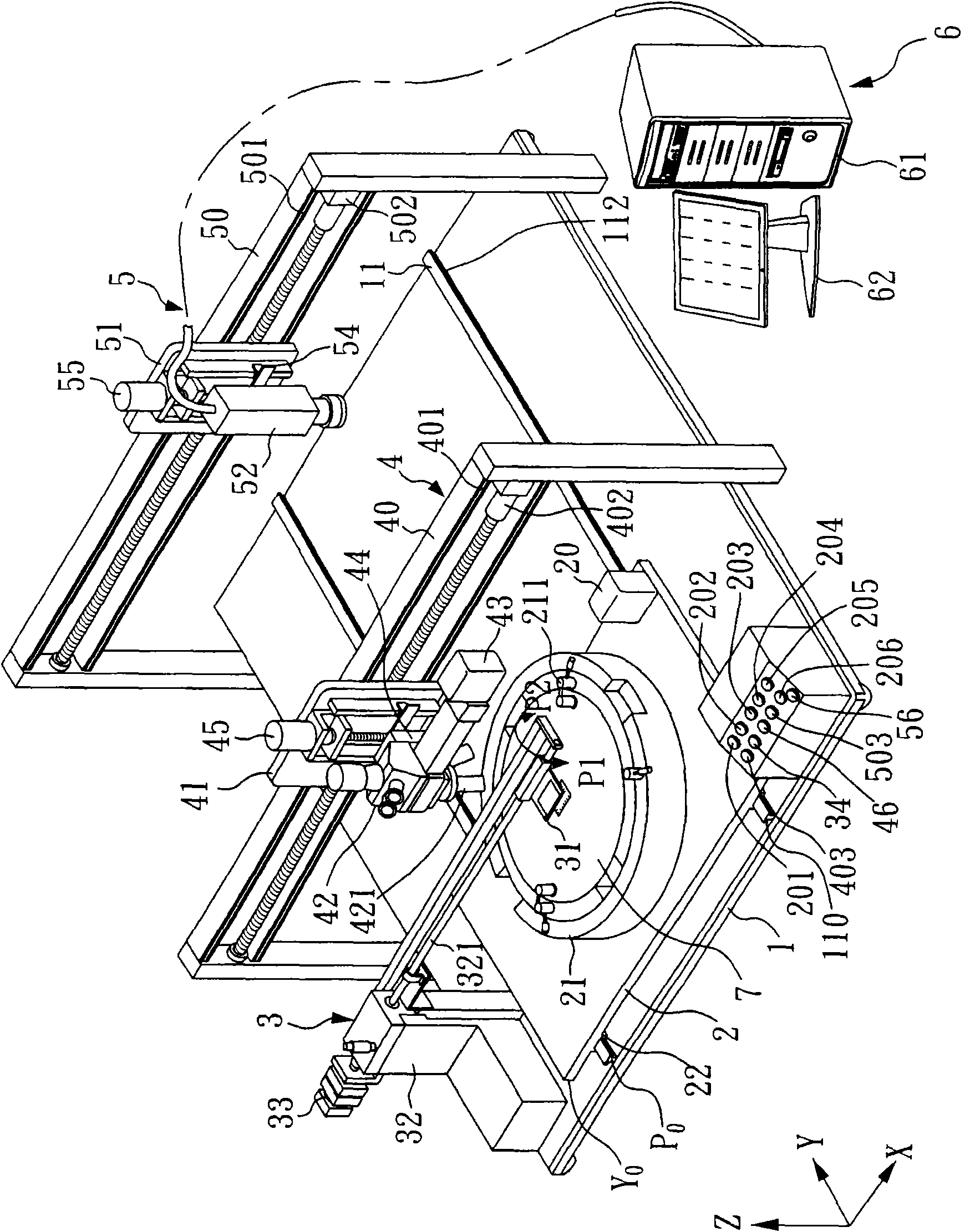
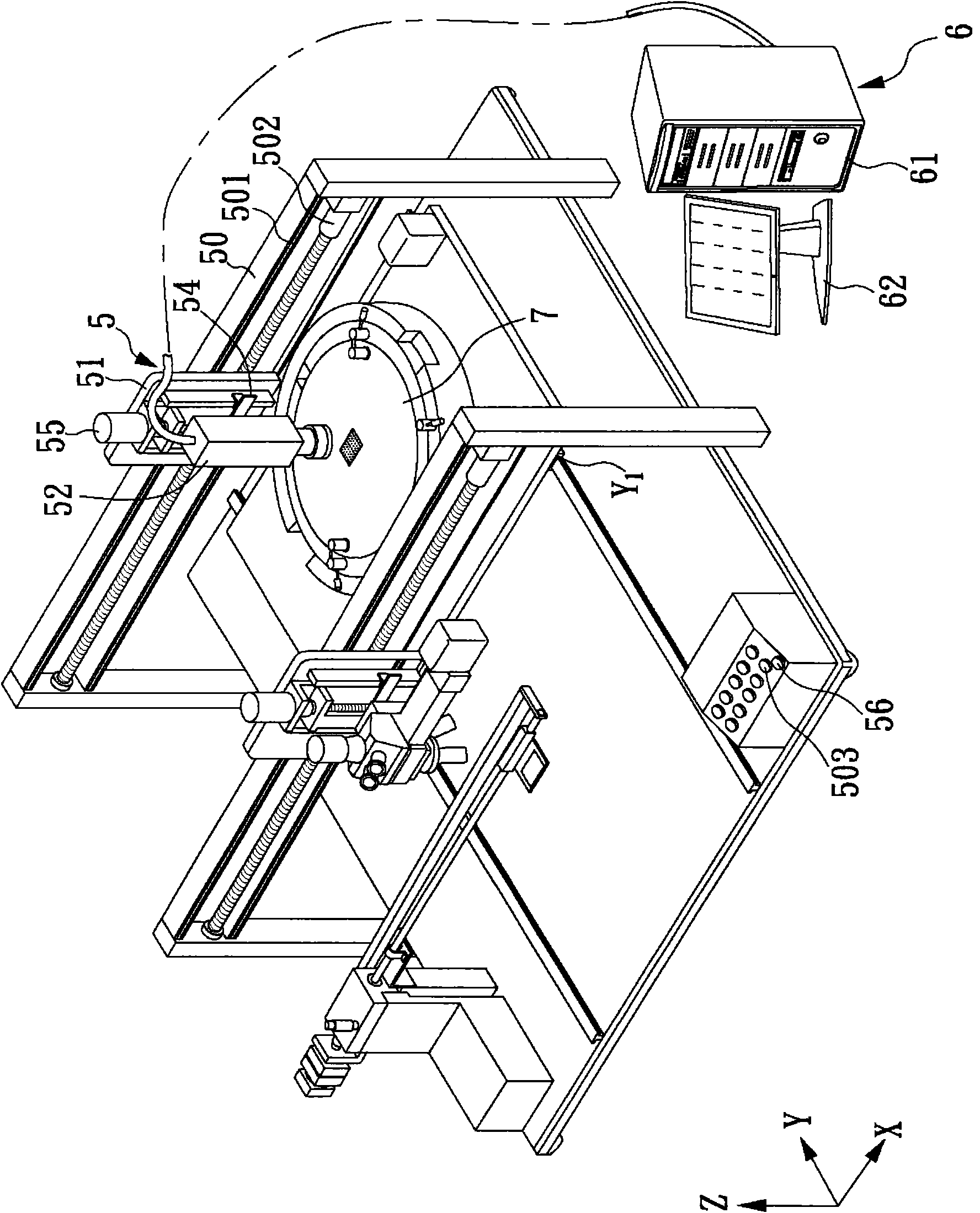
[0043] see figure 1 , is a perspective view of a preferred embodiment of the present invention. As shown in the figure, this embodiment relates to a probe card calibration device, which includes a base 1, a mobile platform 2, a comparison device 3, a microscopic device 4, and a height measurement device 5.

[0044] The base 1 includes a first guiding device, and the first guiding device includes a first end 110 and a second end 112 , wherein the first guiding device refers to two sliding rails 11 . The mobile platform 2 includes a second guide device and a rotating platform 21, wherein the second guide device refers to two sliding seats 22, which relatively slide on the two slide rails 11, and the mobile platform 2 passes through the second guide The two sliding seats 22 of the guiding device are correspondingly slid on the two sliding rails 11 of the first guiding device of the base 1, and relatively slide between the first end 110 and the second end 112, and the rotating s...


PUM


Abstract

The invention relates to a probe card corrector, wherein a movable platform can slide to a position below a microdevice and a height measurer by a first guidance device on a base, and a probe card is fixedly clamped on the movable platform. The probe card corrector can adopt the following steps for correcting the probe card: carrying out the work of longitudinal and transversal correction and pin regulation on a probe card on the movable platform by using the microdevice and a comparator, moving the movable platform to the position below the height measurer along the first guidance device, continuously measuring the height of the probe card by using the height measurer, and recording the height of each probe through a controller. The process is repeatedly carried out in the way, the pin regulator can accurately, conveniently and rapidly complete the work of the correction of the probe card on the same pin regulation machine.

Description

technical field [0001] The invention relates to a calibration device, in particular to a calibration device suitable for a probe card. Background technique [0002] Probe card calibration can be divided into calibration of longitudinal and lateral deflection of the probe, and calibration of the average height of the probe. When performing vertical and horizontal corrections, use a low-magnification microscope and a comparison cover to compare the probe cards. At this time, if the probe is deviated vertically or horizontally relative to the comparison mark on the comparison cover, the vertical and horizontal corrections will be manually performed, and this correction will continue until the probe is correctly aligned with the comparison mark. If the average height of the probes is corrected, a high-magnification microscope is used for correction, and the height of the probes protruding or recessed from the average height is adjusted to make the overall probes uniform in heig...

Claims


Application Information

Patent Timeline
Patent Type & Authority Applications(China)
IPC IPC(8): G01B11/02
Inventor 黄钧鸿刘尚达
Owner KING YUAN ELECTRONICS
Why Eureka
Try Eureka