
Correcting machine

A calibration machine and workbench technology, applied in the field of calibration machines, can solve the problems of low efficiency, laborious, low calibration accuracy, etc., and achieve the effect of facilitating stable screw, convenient calibration work, and high calibration accuracy

Inactive Publication Date: 2015-06-03
ZHEJIANG SHUANGDUN TEXTILE TECH CO LTD
View PDF9 Cites 0 Cited by
  • Summary
  • Abstract
  • Description
  • Claims
  • Application Information

AI Technical Summary

Problems solved by technology

[0002] Metal pipe fittings, rods, and metal shafts in factories and mines are often deformed and bent. At present, most of them are calibrated manually by manual methods. The operating procedures are not standardized, time-consuming, laborious, inefficient, and the calibration accuracy is low.

Method used


Image

  • Correcting machine
  • Correcting machine
  • Correcting machine

Examples


Embodiment Construction

[0018] Embodiments of the present invention will be further described below in conjunction with the accompanying drawings.

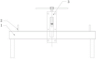
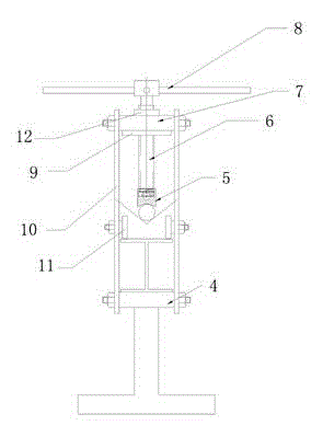
[0019] A calibration machine, characterized in that it includes a workbench 1, a pressure device 3 installed on the workbench 1 for pressing the workpiece to be calibrated, and a pressure device 3 arranged on the workbench 1 at both ends of the pressure device 3 for supporting the workpiece to be calibrated The support block 2, the pressure device 3 includes two support plates 10; the lower end of the support plate 10 is fixed with two lower force rods 4 on the lower surface of the workbench 1, and the upper end of the support plate 10 is fixed with two upper Stress bar 7; the support plate 10 is fixed with a limit guide device located on the upper surface of the workbench 1; the upper force bar 7 is fixed with a nut support frame; the nut support frame is fixed with a nut 12; The nut 12 is internally screwed with a screw 6 ; the upper end of the screw 6...


PUM


Abstract

The invention discloses a correcting machine which comprises a worktable (1), a pressure device (3) mounted on the worktable (1) and used for pressing a work piece to be corrected, and supporting blocks (2) arranged at the two ends of the pressure device (3) on the worktable (1) and used for supporting the work piece to be corrected, wherein the pressure device (3) comprises two supporting plates (10); two upper force bearing rods (7) are fixed at the upper ends of the supporting plates (10); a nut supporting frame is fixed on the upper force bearing rods (7); a nut (12) is fixed on the nut supporting frame; a screw rod (6) is screwed in the nut (12); and a wrenching rod (8) is fixed at the upper end of the screw rod (6). Through rotating the wrenching rod, the screw rod is enabled to rotate downwards and rotary motion of a work piece pressing head is converted to linear downward motion, so that the work piece to be corrected is extruded and the aim of correcting the work piece can be achieved. The correcting machine has a simple structure, is convenient to operate, saves time and labor and achieves high correction accuracy.

Description

technical field [0001] The invention belongs to the field of mechanical manufacturing, in particular to a calibration machine. Background technique [0002] Metal pipe fittings, rods, and metal shafts in factories and mines are often deformed and bent. At present, most of them are calibrated manually by manual methods. The operating procedures are not standardized, time-consuming, laborious, inefficient, and the calibration accuracy is low. Contents of the invention [0003] The technical problem to be solved by the present invention is to provide a calibration machine with simple structure, convenient operation, time saving, labor saving and high calibration accuracy. [0004] The technical solution of the present invention is: a calibration machine, which includes a workbench, a pressure device installed on the workbench for pressing the workpiece to be calibrated, and support blocks arranged on the workbench at both ends of the pressure device for supporting the workpie...

Claims


Application Information

Patent Timeline
Patent Type & Authority Patents(China)
IPC IPC(8): B21D3/10
Inventor 胡长明谢军
Owner ZHEJIANG SHUANGDUN TEXTILE TECH CO LTD
Learn More