
Engine correction system for correcting controlled variables of actuator

A technology of engines and actuators, which is applied in the directions of machines/engines, engine control, electrical control, etc., and can solve problems such as performance parameters deviating from optimal target values, performance parameter interference, and parameter calibration accuracy drop

Inactive Publication Date: 2015-04-29
DENSO CORP
View PDF4 Cites 0 Cited by
  • Summary
  • Abstract
  • Description
  • Claims
  • Application Information

AI Technical Summary

Problems solved by technology

[0003] The above prior art calibration systems are designed to perform parameter calibration based on the correlation between performance parameters and controlled parameters, however, it may cause interference (or compromise) between performance parameters because when one of the performance parameters When reaching its optimal target value, another performance parameter will deviate from its optimal target value
There are some practical limitations to completely eliminating these interferences, which can lead to concerns about the repetition of parameter calibrations or the loss of accuracy of parameter calibrations

Method used


Image

  • Engine correction system for correcting controlled variables of actuator
  • Engine correction system for correcting controlled variables of actuator
  • Engine correction system for correcting controlled variables of actuator

Examples


Embodiment Construction

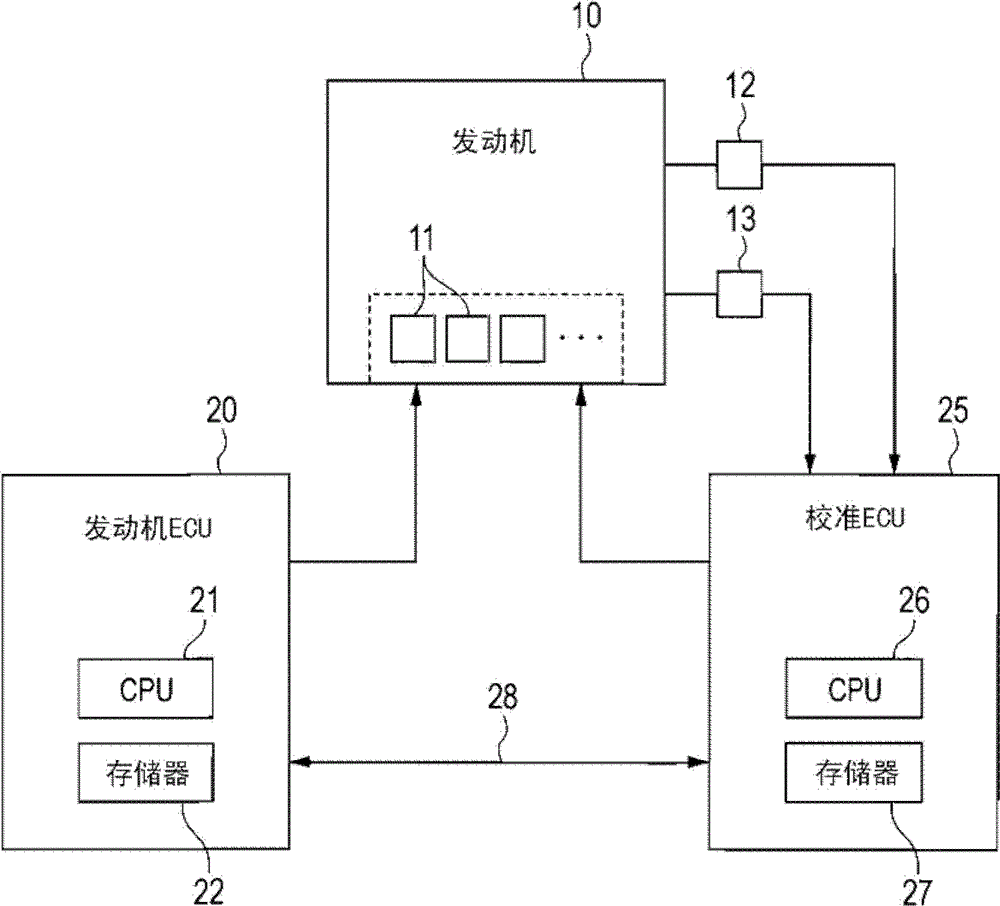
[0021] Referring to the drawings, in which like reference numerals denote like parts throughout the several views, in particular figure 1 (a), shows the engine calibration system according to the first embodiment, which is designed to realize the calibration of different types of control tasks, to obtain calibration values ​​(ie, optimal values) and store them in the engine In the memory of the ECU (Electronic Control Unit) 20 .

[0022] The engine calibration system is also used as an engine control system of the internal combustion engine 10 installed in a motor vehicle. The following discussion will refer to a self-ignition diesel engine as an example in which fuel is injected under high pressure into four cylinders #1 to #4. The engine 10 has installed therein an actuator 11 for controlling the operation of the engine 10 at a desired operating condition. The actuator 11 installed in the fuel system is, for example, a fuel injector that injects fuel to the engine 10, and ...


PUM


Abstract

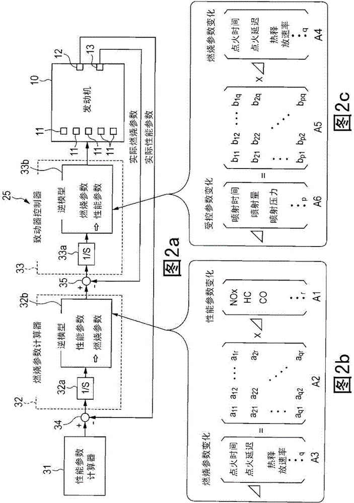
The machine calibration device has a desired behavior parameter-determining circuit which determines a target value of each of multiple behavioral parameters that reflect different types of behavior of an internal combustion engine (10). A target combustion parameter-determining circuit is provided to determine the target value of multiple combustion parameter on the basis of target value of behavioral parameters under using correlation data. The correlation data reflects the correlation between the behavioral parameters and the combustion parameters.

Description

technical field [0001] The present disclosure generally relates to an engine calibration system applicable to a motor vehicle and designed to optimize or calibrate controlled variables of actuators installed in the engine. Background technique [0002] Engine calibration systems for controlling internal combustion engines are known which are designed to make performance parameter values ​​indicative of engine performance (e.g., the amount of NOx or CO emitted from the engine and the fuel consumption in the engine) under given calibration conditions ) coincides with its optimal target value, wherein the calibration conditions are changed sequentially to find the optimal value of the controlled parameters such as the amount of fuel injected into the engine and the injection time. Japanese Patent First Publication No. 2006-118516 teaches determining the order and direction in which different types of controlled parameters are to be changed in order to reduce the value of a perf...

Claims


Application Information

Patent Timeline
Patent Type & Authority Patents(China)
IPC IPC(8): F02D45/00
CPCF02D37/02F02D41/0047F02D41/2432F02D2041/1434
Inventor 池田纯孝石塚康治樋口和弘中辻勇贵
Owner DENSO CORP
Learn More