Method for dynamically determining a clutch rest point

A static point and dynamic technology, applied to clutches, mechanical equipment, etc., can solve problems such as increased wear, temperature rise, and torque increase, and achieve the effect of improving reality

Inactive Publication Date: 2010-01-20
ZF FRIEDRICHSHAFEN AG
View PDF1 Cites 4 Cited by
  • Summary
  • Abstract
  • Description
  • Claims
  • Application Information

AI Technical Summary

Problems solved by technology

From this point onwards, the torque transferable by the clutch increases sharply as the clutch continues to close, so that small thermal expansions or other influences of the clutch components and / or adjusting means cause a significant increase in the transferable torque and The frictional heat generated during the movement increases significantly, and thus sharply increases wear and causes further heating

Method used


Image

  • Method for dynamically determining a clutch rest point
  • Method for dynamically determining a clutch rest point

Examples


Embodiment Construction

[0056] The following exemplary embodiment is based on the fact that the motor vehicle has an internal combustion engine, the output shaft of which is connected in a rotationally fixed manner to the transmission side of the multi-disk clutch. Single-plate or double-plate clutches of a corresponding operating principle can likewise be used. The output side of the multi-plate clutch is non-rotatably connected to the input shaft of the automatic transmission. The type of operation of the multi-plate clutch is determined by the setting position of the clutch actuator, which is controlled by the electronic control unit.

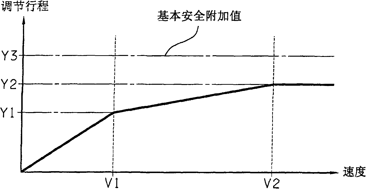
[0057] The basic resting point of the clutch is determined for the first time at the end of the vehicle production line and subsequently repeated for the clutch, for example at a workshop inspection, at an actuator adjustment value of 27 mm, for example. The control value can be determined, for example, by slowly closing the clutch when the engine output shaft is ...


PUM


Abstract

The invention relates to a method for determining a rest point of a clutch, for example a multiple-disc clutch, in a dynamic and event-dependent fashion. The rest point is here an actuation path point or an actuation path region just before the slip region of the clutch in which the clutch still cannot transmit any appreciable torque but which permits a position of the clutch, in which an appreciable torque can be transmitted, to be reached very quickly. According to one preferred variant, the rest point can be determined on the basis of a basic rest point by taking into account various offset values or correction values. A control device determines these correction values in this context at favourable, event-dependent times, for example during or shortly after the disengagement of a gear speed, as a function of specific parameters such as, for example, an original gear speed and / or a target gear speed and / or the type of gear shifting operation, for example, shifting up, shifting down or shifting out of the neutral position of the transmission. A clutch actuator is then activated in such a way that the friction clutch is closed up to the clutch rest point. This makes it possible to minimize, as a function of the specific parameters, both increased wear of the clutch and a required switching time until a slip region of the clutch is reached.

Description

[0001] The invention relates to a method for dynamically calculating the rest point position of an automatic or automatable friction clutch, wherein a control device controls a clutch actuator in such a way that an actuator of the clutch actuator Assume the corresponding actuator position and thereby adjust the controllable torque transmission between the transmission shaft coupled to the transmission motor and the output side of the friction clutch, wherein the control device is used for the transmission of rotation When preparing to close the friction clutch for the purpose of torque, first adjust the actuator of the clutch actuator to the position of the static point. At the position of the static point, compared with the fully open clutch, the dead stroke of the friction clutch until the transmission torque is greatly reduced. Small. Background technique [0002] Friction clutches have long been used in various related fields and are generally known. Especially in the fie...

Claims


Application Information

Patent Timeline
Patent Type & Authority Applications(China)
IPC IPC(8): F16D48/06
CPCF16D2500/50251F16D2500/3108F16D48/068F16D2500/1112F16D2500/30806F16D2500/10412F16D2500/70414
Inventor 安东尼·罗伯特·萨伊曼
Owner ZF FRIEDRICHSHAFEN AG
Why Eureka
Try Eureka