U-type pipe locking device

A technology of locking device and U-shaped tube, which is applied in the direction of feeding device, positioning device, storage device, etc., can solve the problems of not being able to clamp the pipe fitting, poor use effect, and pipe fitting detachment, etc., and achieve the effect of simple structure

Active Publication Date: 2010-01-27
OMS MASCH CO LTD
View PDF0 Cites 11 Cited by
  • Summary
  • Abstract
  • Description
  • Claims
  • Application Information

AI Technical Summary

Problems solved by technology

[0002] At present, the bases that cooperate with U-shaped tubes generally only have a U-shaped groove that is matched with the U-shaped tube on the base, but because the bottom of the tube is only placed in the U-shaped groove, the tube cannot be clamped, and the tube is very It is easy to change the length, so that the pipe fittings are out of the U-shaped groove, and the use effect is not good

Method used


Image

  • U-type pipe locking device
  • U-type pipe locking device
  • U-type pipe locking device

Examples


Embodiment Construction

[0022] Below in conjunction with accompanying drawing and specific embodiment the present invention is described in further detail:

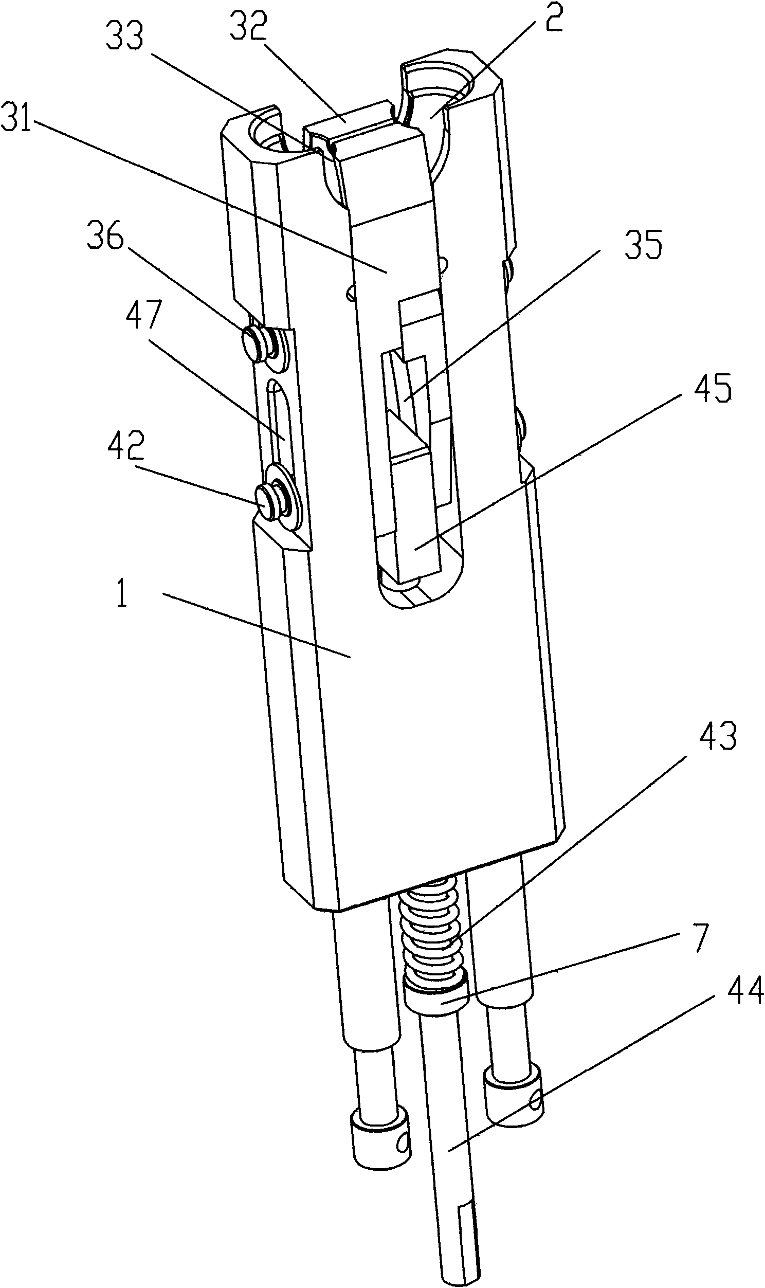
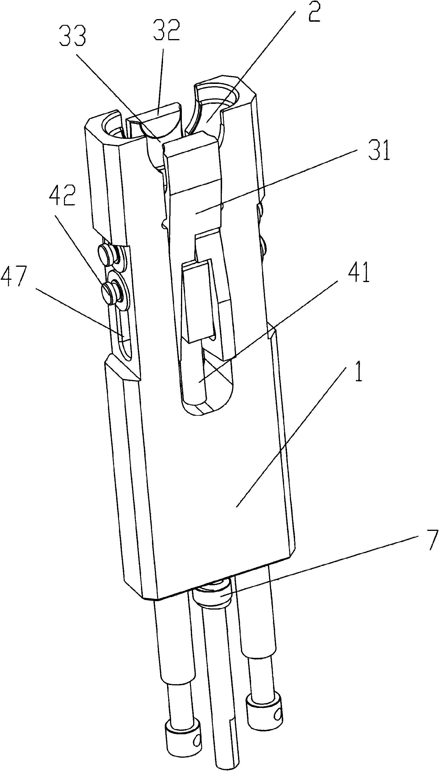
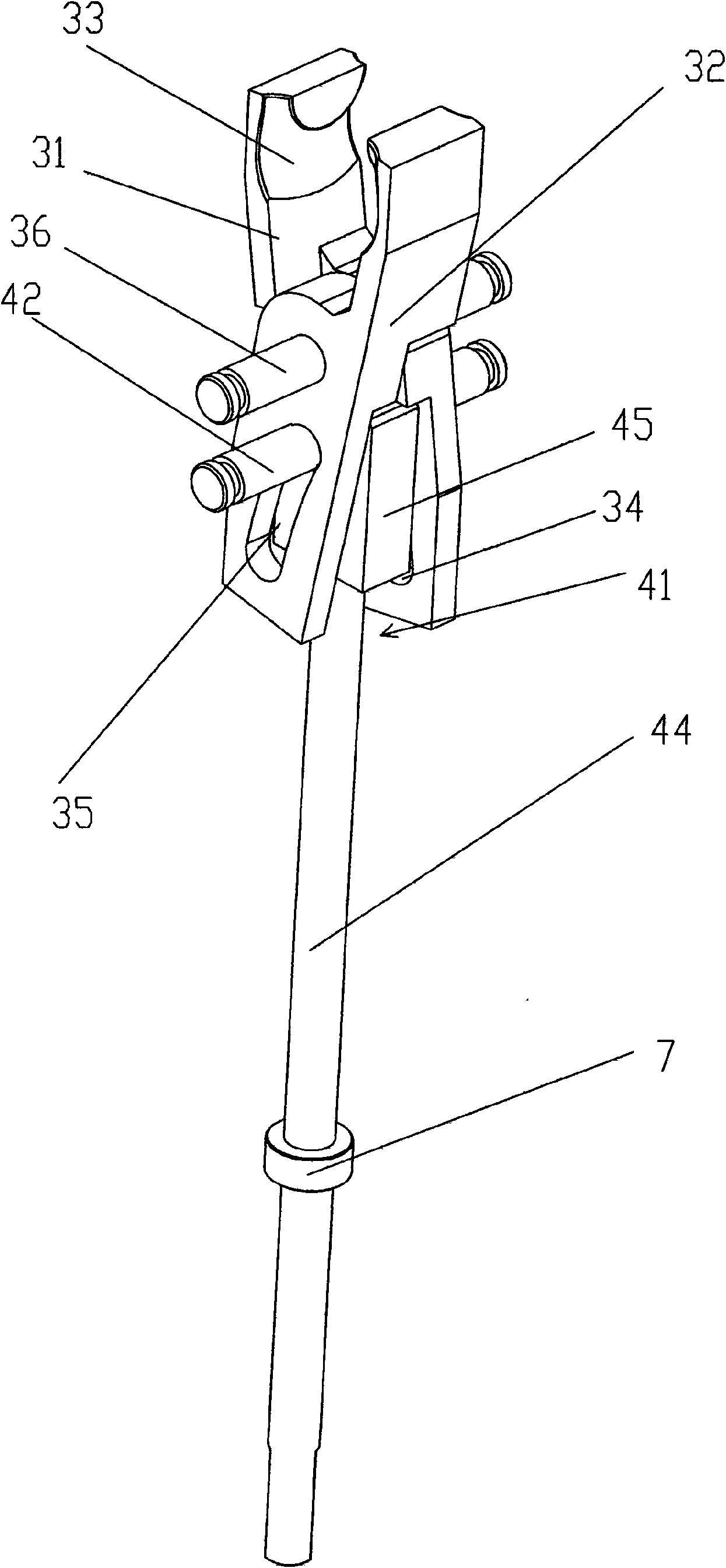
[0023] A U-tube locking device such as figure 1 , 7 , 8, it is set on the tube expander, including a base 1, the head of the base 1 is provided with a U-shaped groove 2 that is matched with the U-shaped tube 8, and a U-shaped groove 2 that can be clamped and placed in the base 1 is provided. The clamping device 3 of the pipe fitting in the U-shaped groove 2 and matched with the pipe fitting can put the bottom of the U-shaped pipe 8 in the U-shaped groove 2, and the clamping device 3 can clamp the bottom of the U-shaped pipe 8 simultaneously.

[0024] Such as figure 2 , 3 , 6, the clamping device 3 includes a positioning shaft 36 arranged on the base 1, and two symmetrical left and right clamping blocks 31, 32 are hinged on the positioning shaft 36. The heads of the right clamping blocks 31, 32 are respectively provided with grooves 33 which...


PUM


Abstract

The invention relates to a U-type pipe locking device. The locking device comprises a pedestal, wherein the head of the pedestal is provided with a U-type groove matched with the U-type pipe. The locking device is characterized in that the inside of the pedestal is provided with a clamping device which is capable of clamping a pipe piece placed inside the U-type groove and meshed with the pipe piece; the clamping device comprises a positioning shaft arranged on the pedestal; the positioning shaft is hinged with a left clamping block and a right clamping block which are symmetrical; the heads of the left clamping block and the right clamping block are respectively provided with a groove matched with the U-type pipe; and the tail ends of the left clamping block and the right clamping block are provided with push rod components capable of driving both clamping blocks to open and close. The invention aims to provide the U-type pipe locking device which has simple structure and can conveniently clamp a pipe piece placed inside the U-type groove.

Description

【Technical field】 [0001] The invention relates to a U-shaped tube locking device, in particular to a U-shaped tube locking device applied in a tube expander. 【Background technique】 [0002] At present, the bases that cooperate with U-shaped pipes generally only have a U-shaped groove that is matched with the U-shaped pipe on the base, but because the bottom of the pipe is only placed in the U-shaped groove, the pipe fittings cannot be clamped, and the pipe fittings are very It is easy to change the length, so that the pipe fittings are separated from the U-shaped groove, and the use effect is not good. 【Content of invention】 [0003] The invention overcomes the disadvantages of the prior art and provides a U-shaped pipe locking device which is simple in structure and conveniently clamps the pipe fittings placed in the U-shaped groove. [0004] In order to solve the above-mentioned technical problems, the present invention adopts the following technical solutions: [0005...

Claims


Application Information

Patent Timeline
Patent Type & Authority Applications(China)
IPC IPC(8): B21D43/00B21D39/08
Inventor 龙晓斌
Owner OMS MASCH CO LTD
Why Eureka
Try Eureka