Rolling element retaining chain unit

A technology of rolling elements and holding chains, which is applied in the direction of linear motion bearings, bearings, shafts and bearings, etc., can solve problems such as unstable jumping, unsteady operation, etc., and achieve the effect of increasing tensile strength

Inactive Publication Date: 2011-05-25
CHIEFTECH PRECISION
View PDF3 Cites 0 Cited by
  • Summary
  • Abstract
  • Description
  • Claims
  • Application Information

AI Technical Summary

Problems solved by technology

And the closed circulation guide groove of the circulation channel is always combined by more than two parts, so when each wrinkle end point passes through the joint, it will cause unstable jumping, and therefore the operation cannot be smooth and smooth

Method used


Image

  • Rolling element retaining chain unit
  • Rolling element retaining chain unit
  • Rolling element retaining chain unit

Examples


Embodiment Construction

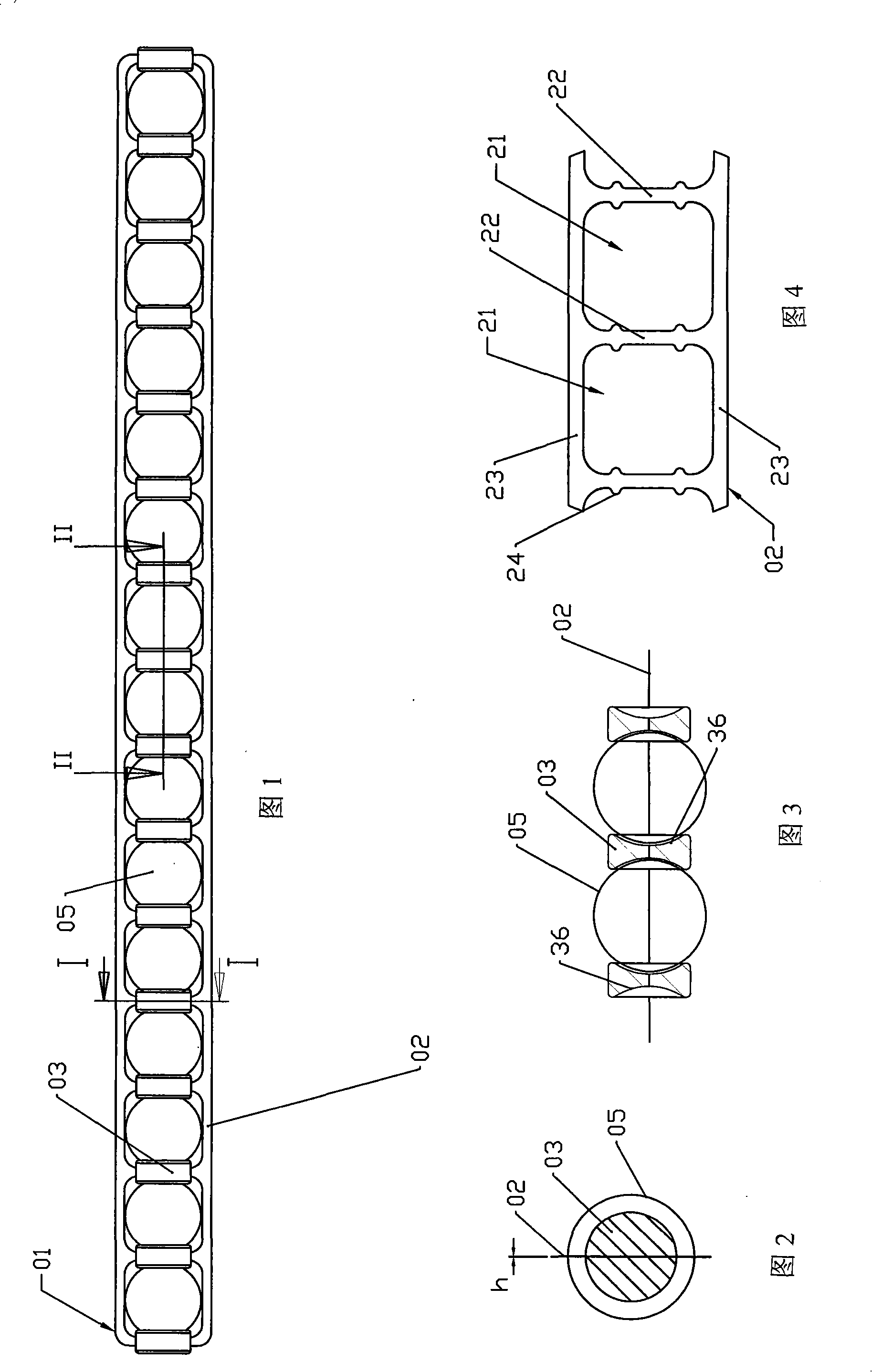
[0075] Such as figure 1 , figure 2 As shown, a rolling element retaining chain 01 is designed to consist of a flexible metal sheet 02 and a plurality of spacers 03 , wherein the flexible metal sheet 02 has holes 21 arranged axially. Such as Figure 4 As shown, a horizontal bar 22 is formed between the holes 21 to separate the two holes 21, and the spacer block 03 is combined on the horizontal bar 22; a connecting bar 23 is formed on the upper and lower sides of the hole 21, and all the horizontal bars 22 are connected to the connecting bar 23 Above: a row of rolling elements, including a plurality of rolling elements 05, each rolling element 05 is held in each hole 21 and separated by two spacers 03; as image 3 As shown, the surface of the spacer block 03 corresponding to the rolling body 05 is in a covered shape 36, and the rolling body 05 is held in the rolling body holding chain 01 between the two spacer blocks 03 that are in a covered shape 36 on the left and right an...


PUM


Abstract

The invention discloses a rolling element retaining chain unit. A rolling element retaining chain provides rows of rolling elements to smoothly run in a circulating channel, and a fixed space is kept between two adjacent rolling elements mutually, so that the rolling elements cannot collide mutually. The rolling element retaining chain consists of at least one flexible sheet metal and a pluralityof spacing blocks, wherein the sheet metal is provided with axially arranged holes, and a cross element is formed between two holes to separate the two holes; the spacing blocks are combined onto thecross elements; the strength of the flexible sheet metal is far higher than that of the commonly used plastic material, and the sheet metal can bear higher tension and cannot break, so the metal sheet can better ensure the durability of the rolling element retaining chain; besides, the thickness of the metal sheet is small, two end parts of the sheet metal can be overlapped and fixed and cannot generate interference, and the enclosed rolling element retaining chain is formed.

Description

technical field [0001] The present invention is a rolling element retaining chain unit applied in a linear motion mechanism. An axially extending and elastic rolling element retaining chain holds a plurality of axially extending rolling elements in a row, and is positioned between two adjacent rolling elements. If a certain distance is maintained between the rolling elements, the rolling element retaining chain and the rolling elements can circulate smoothly in the circulation channel provided by the linear motion mechanism such as linear slide rail or ball screw. Background technique [0002] The existing linear motion mechanism has a moving part and an axially extending guide part; the moving part and the guiding part each provide at least one row of tracks corresponding to each other to form a running channel; the moving part also provides each row of corresponding tracks One return channel and two return channels, the return channel connects the return channel and the en...

Claims


Application Information

Patent Timeline
Patent Type & Authority Patents(China)
IPC IPC(8): F16C29/04
Inventor 许明哲陈丽芬
Owner CHIEFTECH PRECISION
Why Eureka
Try Eureka