Vacuum motor

A vacuum motor and rotor technology, applied in the direction of intermeshing engines, engine components, machines/engines, etc., can solve problems such as inability to rotate, claws stuck, stuck, etc., to achieve the effect of extending the running time

Pending Publication Date: 2021-09-28
信强(宁波)半导体设备制造有限公司
View PDF0 Cites 0 Cited by
  • Summary
  • Abstract
  • Description
  • Claims
  • Application Information

AI Technical Summary

Problems solved by technology

[0002] When the existing claw rotor used for vacuum motors is running, because the claws of the claw rotor and the vacuum motor cylinder are mostly tightly fitted, there is no extra space between the two to accommodate the foreign matter mixed in the air when the vacuum motor is running. , and because of the air flow, most of this kind of foreign matter will be stuck between the claw and the cylinder wall of the vacuum motor, causing the claw to be stuck by foreign matter and unable to rotate. There is a need for improvement in use.

Method used


Image

  • Vacuum motor
  • Vacuum motor
  • Vacuum motor

Examples


Embodiment Construction

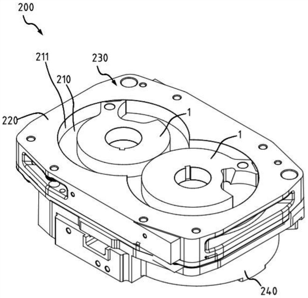
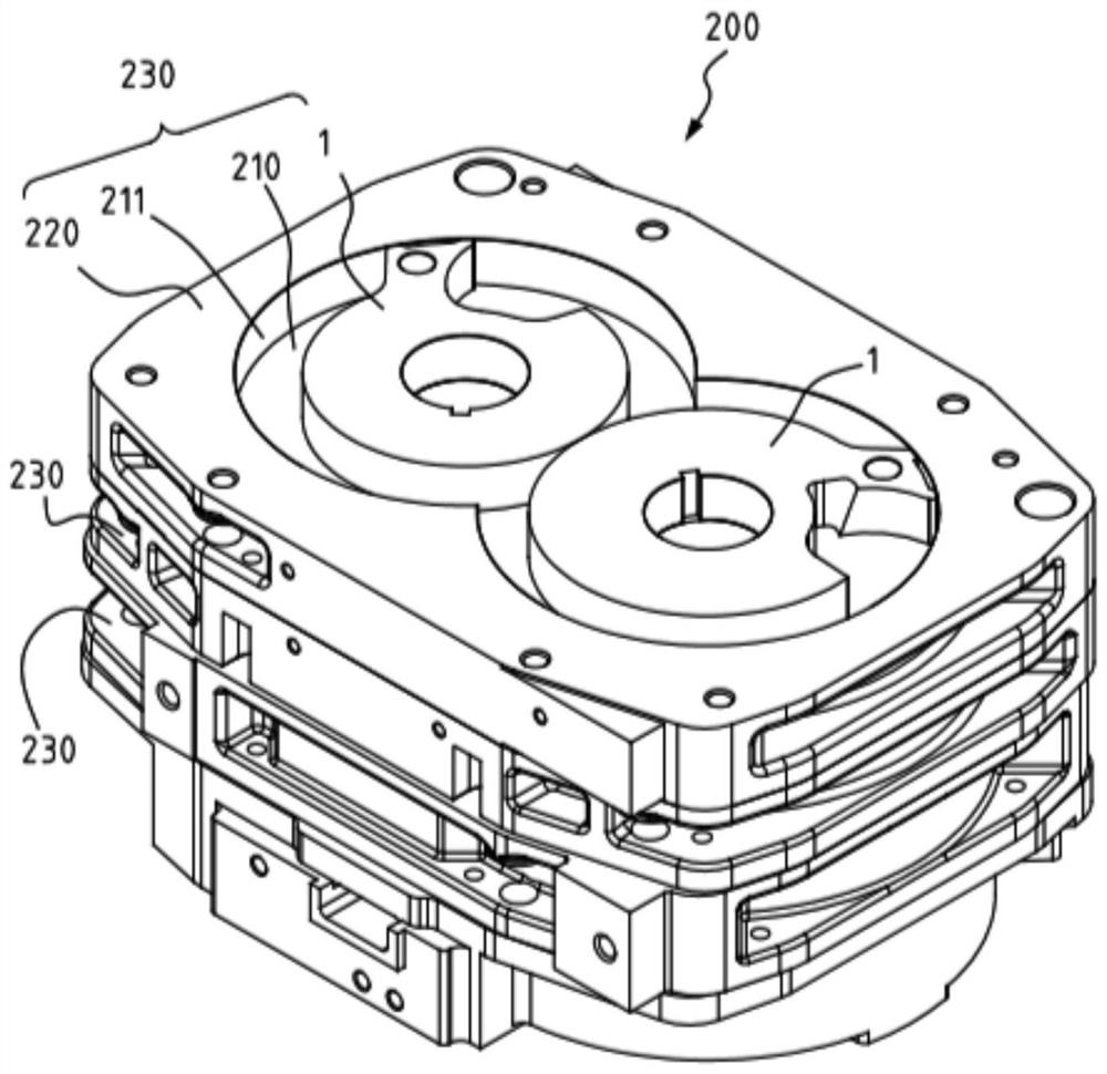
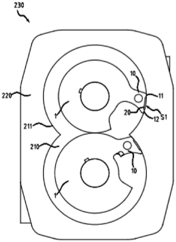
[0030] In order to make the above objects, features and advantages of the present invention more comprehensible, preferred specific embodiments are described as follows. Please refer to the following Figure 1A , Figure 1B and figure 2 , a perspective view of an embodiment of the vacuum motor of the present invention, a schematic diagram and a top view of an embodiment of the vacuum motor excluding the first layer of the vacuum motor rotor combination cylinder and partition.

[0031] As indicated in this application and claims, the terms "a", "an", "an" and / or "the" do not refer to the singular and may include the plural unless the context clearly indicates an exception. Generally speaking, the terms "comprising" and "comprising" only suggest the inclusion of clearly identified steps and elements, and these steps and elements do not constitute an exclusive list, and the method or device may also contain other steps or elements.

[0032] like Figure 1A and figure 2 As sh...


PUM


Abstract

The invention discloses a vacuum motor which comprises a base and a vacuum motor rotor combination, the vacuum motor rotor combination comprises a cylinder, two claw-shaped rotors are arranged on the cylinder, the cylinder comprises a cylinder wall, and each claw-shaped rotor comprises a claw part and a recessed part. The recessed part is arranged on the claw part and forms a dodging space with the cylinder wall. A partition plate covers the cylinder and the two claw-shaped rotors to form the vacuum motor rotor combination.

Description

technical field [0001] The present invention relates to a vacuum motor, especially a vacuum motor capable of forming a dodging space with the cylinder wall to improve the deposition of gaseous foreign matter when the claw rotor is running. Background technique [0002] When the existing claw rotor used for vacuum motors is running, because the claws of the claw rotor and the cylinder of the vacuum motor are mostly tightly fitted, there is no extra space between the two to accommodate the foreign matter mixed in the air when the vacuum motor is running. , and because of the air flow, most of these foreign objects will be stuck between the claws and the cylinder wall of the vacuum motor, causing the claws to be stuck by foreign objects and unable to rotate. There is a need for improvement in use. Contents of the invention [0003] The main purpose of the present invention is to provide a vacuum motor which can form a dodging space with the cylinder wall to improve the deposi...

Claims


Application Information

Patent Timeline
Patent Type & Authority Applications(China)
IPC IPC(8): F01C1/12F01C21/08F01C21/10
CPCF01C1/12F01C21/08F01C21/10
Inventor 顾崇诚
Owner 信强(宁波)半导体设备制造有限公司
Why Eureka
Try Eureka