Electronic device and control method thereof

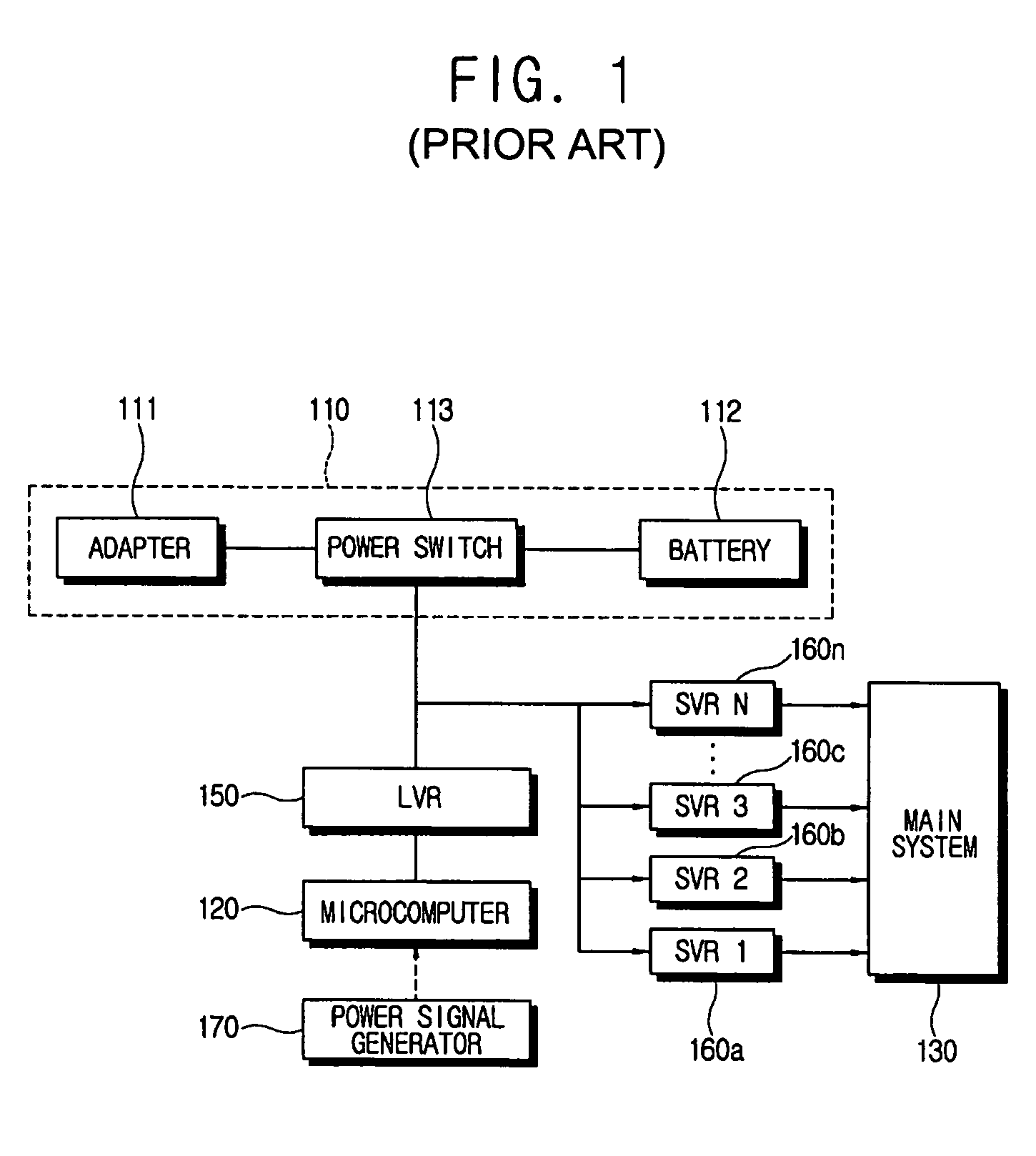
a technology of electronic devices and control methods, applied in the direction of separation processes, instruments, filtration separation, etc., can solve the problems of high power consumption due to control circuits and switching voltage regulators, inability to reduce power loss, and low power-transformation efficiency of linear voltage regulators b>150/b>, etc., to achieve the effect of increasing the running time and the life of batteries, increasing the power required to drive electronic devices, and relatively low power requirements

Active Publication Date: 2005-12-01
SAMSUNG ELECTRONICS CO LTD
View PDF7 Cites 38 Cited by
  • Summary
  • Abstract
  • Description
  • Claims
  • Application Information

AI Technical Summary

Benefits of technology

[0014] Accordingly, it is an aspect of the present invention to provide an electronic device and a control method thereof, in which power required to drive the electronic device is relatively low such that, for example, in the case of a portable electronic device using a battery, a running time and a life span of a battery are increased.

Problems solved by technology

However, in the conventional power supplying system, where the linear voltage regulator 150 is employed to supply the power required to drive the microcomputer 120, there arises a problem that the low power-transformation efficiency of the linear voltage regulator 150 inherently incurs a heavy power loss.
Particularly, in a portable electronic device, the forgoing unwanted power loss of the power supply system is closely interrelated with the running time of the battery 112 for the portable electronic device, so that technology for reducing the power loss is badly needed even if the power loss is slight.
However, total power consumption due to the control circuit and the switching voltage regulator is greater than that due to the linear voltage regulator, so that the switching voltage regulator is inadequate for supplying the power to the microcomputer.

Method used


Image

  • Electronic device and control method thereof
  • Electronic device and control method thereof
  • Electronic device and control method thereof

Examples


Embodiment Construction

[0047] Reference will now be made in detail to the present preferred embodiments of the present invention, examples of which are illustrated in the accompanying drawings, wherein like reference numerals refer to the like elements throughout. The embodiments are described below in order to explain the present invention by referring to the figures.

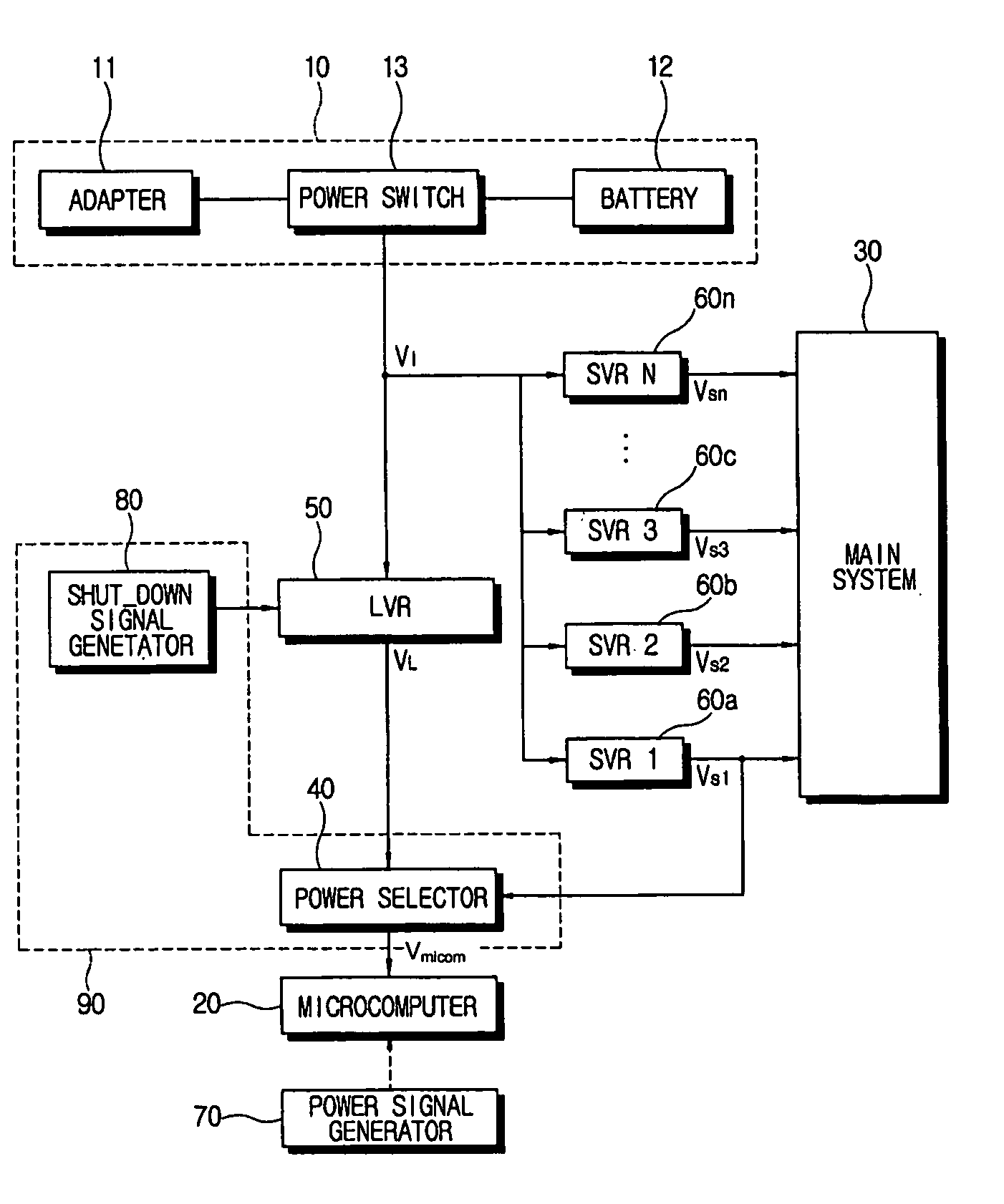
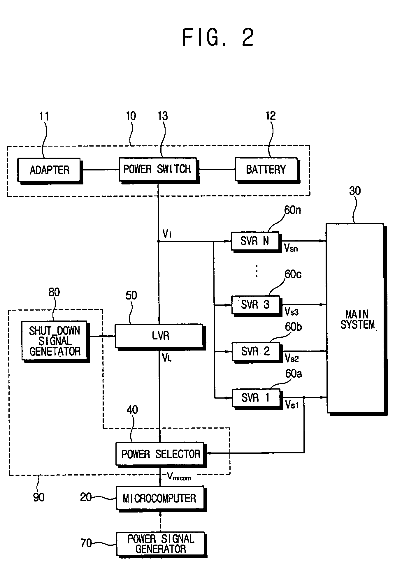
[0048] As shown in FIG. 2, an electronic device according to an embodiment of the present invention comprises a power supply 10, a main system 30, a microcomputer 20, a first regulator 50, a plurality of second regulators 60a, 60b, 60c and 60n, and a controller 90. Here, according to an embodiment of the present invention it is assumed that the first regulator 50 is a linear voltage regulator and each of the second regulators 60a, 60b, 60c and 60n is a switching voltage regulator.

[0049] The power supply 10 supplies power (V1) to drive the electronic device including the main system 30 and / or the microcomputer 20. According to an embodiment...


PUM

PropertyMeasurementUnit
voltageaaaaaaaaaa
voltage levelaaaaaaaaaa
poweraaaaaaaaaa

Abstract

An electronic device with a plurality of electronic components, the electronic device includes a microcomputer, a first regulator supplying power required to drive the microcomputer in a first mode of the electronic device, a second regulator supplying power required to drive at least one among the plurality of electric components in a second mode of the electronic device, and a controller controlling the power from the second regulator to be employed as power for driving the microcomputer when the electronic device operates in the second mode. With this configuration, the electronic device, especially in a case of a portable electronic device using a battery, has a longer running time and a life span of a battery is increased.

Description

CROSS-REFERENCE TO RELATED APPLICATIONS [0001] This application claims the benefit of Korean Patent Application No. 2004-24231, filed Apr. 8, 2004 in the Korean Intellectual Property Office, the disclosure of which is incorporated herein by reference. BACKGROUND OF THE INVENTION [0002] 1. Field of the Invention [0003] The present invention relates to an electronic device and a control method thereof, and more particularly, to an electronic device and a control method thereof, in which power required to drive the electronic device is relatively low, for example, in the case of a portable electronic device using a battery, a running time and a life span of a battery are increased. [0004] 2. Description of the Related Art [0005] Generally, an electronic device employing a battery, for example, a portable computer such as a laptop computer, a notebook computer, a personal digital assistant (PDA) or the like, a mobile phone, a compact disc (CD) player, a video camcorder, etc., has been w...

Claims


Application Information

Patent Timeline
Patent Type & Authority Applications(United States)
IPC IPC(8): G06F1/26H02M3/00G06F1/30G06F1/32
CPCG06F1/3203B01D35/18B01D39/2055B01J20/20C02F1/283B01D69/08C02F1/44
Inventor PARK, HEE-JUN
Owner SAMSUNG ELECTRONICS CO LTD
Why Eureka
Try Eureka