Differential lock assembly

A differential lock and assembly technology, applied in the direction of differential transmission, belt/chain/gear, mechanical equipment, etc., can solve problems affecting product quality, economic loss, etc.

Inactive Publication Date: 2010-01-27
鞠小平
View PDF0 Cites 9 Cited by
  • Summary
  • Abstract
  • Description
  • Claims
  • Application Information

AI Technical Summary

Problems solved by technology

Seriously affected the product quality and brought great economic losses to the enterprise

Method used


Image

  • Differential lock assembly

Examples


specific Embodiment approach

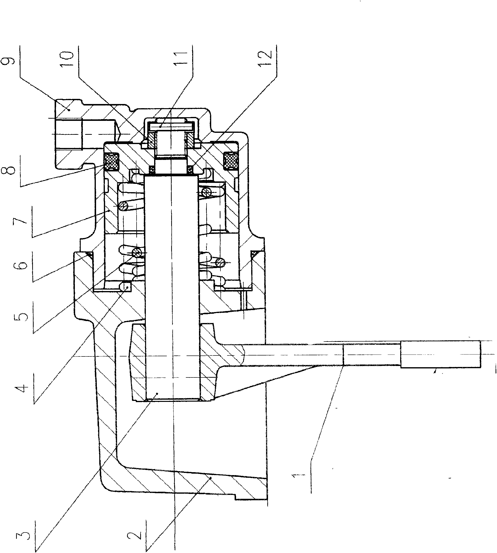
[0006] Specific embodiments: the present invention will be further described below in conjunction with accompanying drawing;

[0007] exist figure 1 Among them, the differential lock assembly is composed of a shift fork 1, a base 2, a shift fork shaft 3, a cylinder 9, and a piston 7. It is characterized in that: the small end of the shift fork shaft 3 is provided with an O-ring 12 and Through the piston 7, it is locked by a small hexagonal flat nut 10, and fixed by an elastic cylindrical pin 11 through the small hexagonal flat nut 10 and the shift fork shaft 3; Two return springs 4, 5 are provided, a leather cup 8 is arranged in the cylindrical groove at the right end of the piston 7, and a shift fork 1 is set on the left end of the shift fork shaft 3 through the base 2; the cylinder 9 pushes the piston 7 Sleeved in the inner cavity, an O-ring is arranged at the connection between the left cylindrical surface of the cylinder 9 and the base. During the specific implementation...


PUM


Abstract

The invention discloses a differential lock assembly, which consists of a shifting fork, a shifting fork shaft, an air cylinder and a piston. A small end of the shifting fork shaft is provided with an O-shaped sealing ring, passes through the piston, is locked by a small hexangular groove-shaped flat nut, and is fixed by an elastic cylindrical pin; the shifting fork shaft in an inner cavity of the piston is provided with two return springs; the inside of a cylindrical groove at the right end of the piston is provided with a leather cup; the left end of the shifting fork shaft passes through a base and is sleeved with the shifting fork; the air cylinder sleeves the piston in the inner cavity; and a connecting position of the cylindrical surface at the left end of the air cylinder and the base is provided with an O-shaped sealing ring. When performing gas tightness check under 0.35-0.8MPa, the differential lock assembly has no gas leakage; the shifting fork has flexible action and return, no blockage phenomenon, and working effective stroke more than 20; and the differential lock assembly meets various technical indexes, and ensures product quality.

Description

Technical field: [0001] The invention relates to auto parts, in particular to a differential lock assembly of auto parts. Background technique: [0002] The current differential lock assembly is checked for air tightness at 0.35-0.8MPa, and there is an air leakage phenomenon, and the movement and return of the shift fork are not flexible, and the phenomenon of stagnation often occurs. The effective stroke of the shift fork is less than 20. It has seriously affected the product quality and brought great economic losses to the enterprise. Invention content: [0003] The purpose of the present invention is to provide a differential lock assembly, which can well overcome the problems existing in the current differential lock assembly. The object of the present invention is achieved in this way. A differential lock assembly is composed of a shift fork, a base, a shift fork shaft, a cylinder, and a piston. It is characterized in that: the small end of the shift fork shaft is p...

Claims


Application Information

Patent Timeline
Patent Type & Authority Applications(China)
IPC IPC(8): F16H48/20F16H48/32
Inventor 潘志东
Owner 鞠小平
Why Eureka
Try Eureka