
Matching method and plasma device applying same

A matching method, plasma technology, applied in the direction of plasma, electrical components, etc., can solve the problems of long matching time, unreasonable matching path, and inability to judge when the plasma starts to glow, etc., to achieve reasonable matching path and short matching time Effect

Active Publication Date: 2012-09-05
BEIJING NAURA MICROELECTRONICS EQUIP CO LTD
View PDF5 Cites 0 Cited by
  • Summary
  • Abstract
  • Description
  • Claims
  • Application Information

AI Technical Summary

Problems solved by technology

[0007] During the matching process, because it is impossible to judge when the plasma starts to glow, the capacitance adjustment may leave the starting zone after entering the starting zone, resulting in repeated adjustments, which makes the matching time longer and the matching path unreasonable

Method used


Image

  • Matching method and plasma device applying same
  • Matching method and plasma device applying same
  • Matching method and plasma device applying same

Examples


specific Embodiment 1

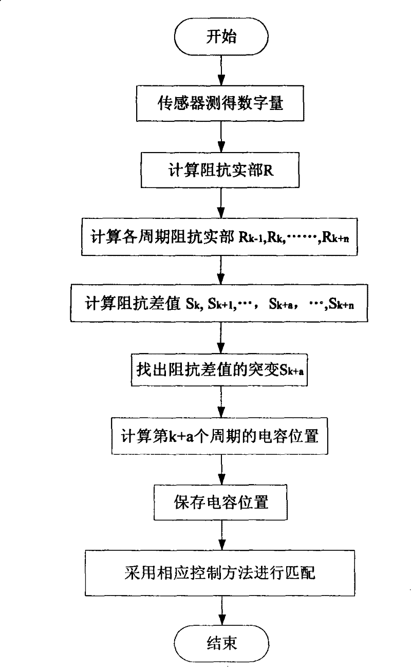
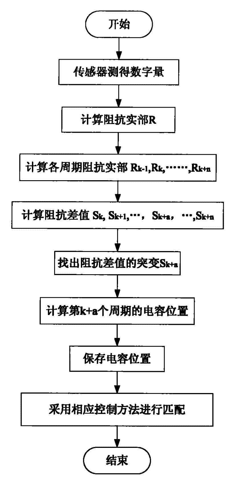
[0028] Specific embodiment one, such as figure 2 As shown, the real part of the impedance is selected as the parameter, and the specific matching process is as follows:

[0029] First, the real part of the impedance in each matching cycle is calculated through the data measured by the sensor. Then, by comparing the difference between the real part of the impedance in each matching cycle and the real part of the impedance in the previous matching cycle, the ignition band of the plasma is obtained, and then the corresponding control method is used for impedance matching, so that the capacitance Adjust within the glow band until a match is achieved.

[0030] The specific implementation principle is:

[0031] According to the digital quantity measured by the sensor, the real part R of the load impedance in each matching cycle is calculated. Set the current matching period of the control software as the kth period, and set the real part of the impedance calculated in the kth pe...

specific Embodiment 2

[0045] In the second embodiment, the imaginary part of the impedance is selected as a parameter, and the specific matching process is as follows:

[0046] In the matching process, under certain process conditions, the value of the imaginary part of the impedance of each matching cycle calculated by the digital quantity measured by the sensor is as follows:

[0047] R 0 * = 64.6139 , R 1 * = 64.5091 , R 2 * = 64.5115 , R 3 * = 64.6267 , R 4 * = 53.6391 , R 5 * = 52.95 , ...


PUM


Abstract

The invention discloses a matching method and a plasma device applying the same. The method comprises the steps of: firstly, calculating a real part or an imaginary part of the resistance through the digital quantity obtained by a sensor, secondly, taking difference values of real parts or imaginary parts of the resistance calculated by various control periods, and comparing the difference valuesto find a mutant difference value, wherein the control period in which the mutant difference value is positioned enters a luminance build-up band of a plasma; and finally, utilizing a corresponding control method to control a capacitor and carry out adjustment in the luminance build-up band until the matching is achieved. The method can ensure that the adjustment of a matcher during the matching is more targeted. The matcher enters the luminance build-up band and then adopts a corresponding mode for matching to avoid the condition of repetitive adjustment near the luminance build-up band, shortens matching time, optimizes matching path, and prolongs the service life of the matcher.

Description

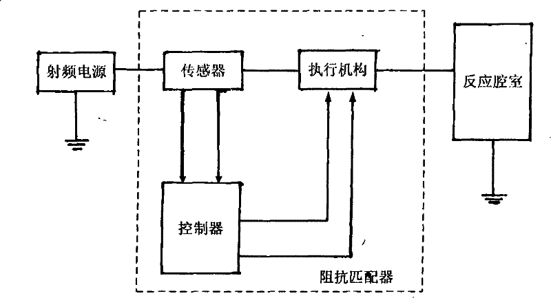
technical field [0001] The invention relates to a plasma generation and control technology, in particular to a matching method and a plasma device using the matching method. Background technique [0002] In an RF (radio frequency) plasma generator, an RF generator with a constant output impedance (usually 50Ω) generates a fixed frequency (usually 13.56MHz) of RF waves to provide RF power to the plasma reaction chamber to excite the Plasma for etching or other processes. Generally speaking, the impedance of the nonlinear load of the plasma chamber is not equal to the constant output impedance of the RF generator, so there is a serious impedance mismatch between the RF generator and the plasma chamber, resulting in a large impedance on the RF transmission line. The reflected power of the RF generator cannot be fully delivered to the reaction chamber. [0003] Such as figure 1 As shown, in order to solve the above problems, an impedance matcher is inserted between the RF gen...

Claims


Application Information

Patent Timeline
Patent Type & Authority Patents(China)
IPC IPC(8): H05H1/46
Inventor 王一帆
Owner BEIJING NAURA MICROELECTRONICS EQUIP CO LTD
Learn More