Equipment containing medium cutting mechanism

A cutting mechanism and medium technology, applied in the direction of metal processing, etc., can solve the problems of low efficiency, troublesome cutting, low cutting quality, etc., and achieve the effect of simple operation, straight cutting seam and high efficiency

Active Publication Date: 2010-02-17
SHENZHEN RUNTIANZHI DIGITAL EQUIP
View PDF0 Cites 3 Cited by
  • Summary
  • Abstract
  • Description
  • Claims
  • Application Information

AI Technical Summary

Problems solved by technology

[0003] In the process of research and practice of the prior art, the inventor of the present invention found that the above-mentioned manual cutting slit is not straight, the cutting quality is not high, affects the appearance, requires the cooperation of many people, and the cutting is cumbersome and inefficient

Method used


Image

  • Equipment containing medium cutting mechanism
  • Equipment containing medium cutting mechanism

Examples


Embodiment 1

[0012] Embodiment 1. In the device containing the medium cutting mechanism, the medium is placed on the medium supporting plate, and the supporting plate gap is set on the medium supporting plate. The medium cutting mechanism includes: a knife holder, a first blade, a first upper Pressing wheel set, the second upper pressing wheel set, the knife rest includes an upper crossbeam and two upper side limbs connected with the upper crossbeam, the first blade is installed on the upper crossbeam of the knife rest, and the The first upper pressure roller group and the second upper pressure roller group are respectively installed on the upper side limbs of the knife holder, straddle the two sides of the supporting plate gap, press the medium, and the supporting plate gap The width is greater than the thickness of the first blade.

[0013] The working principle of the medium cutting mechanism in the equipment is as follows: under the action of gravity, the two pressure wheel sets instal...

Embodiment 2

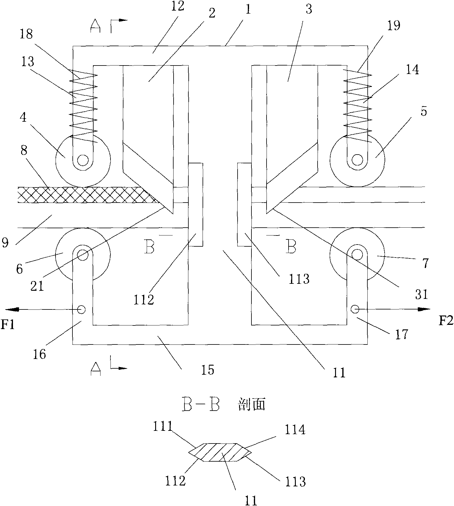
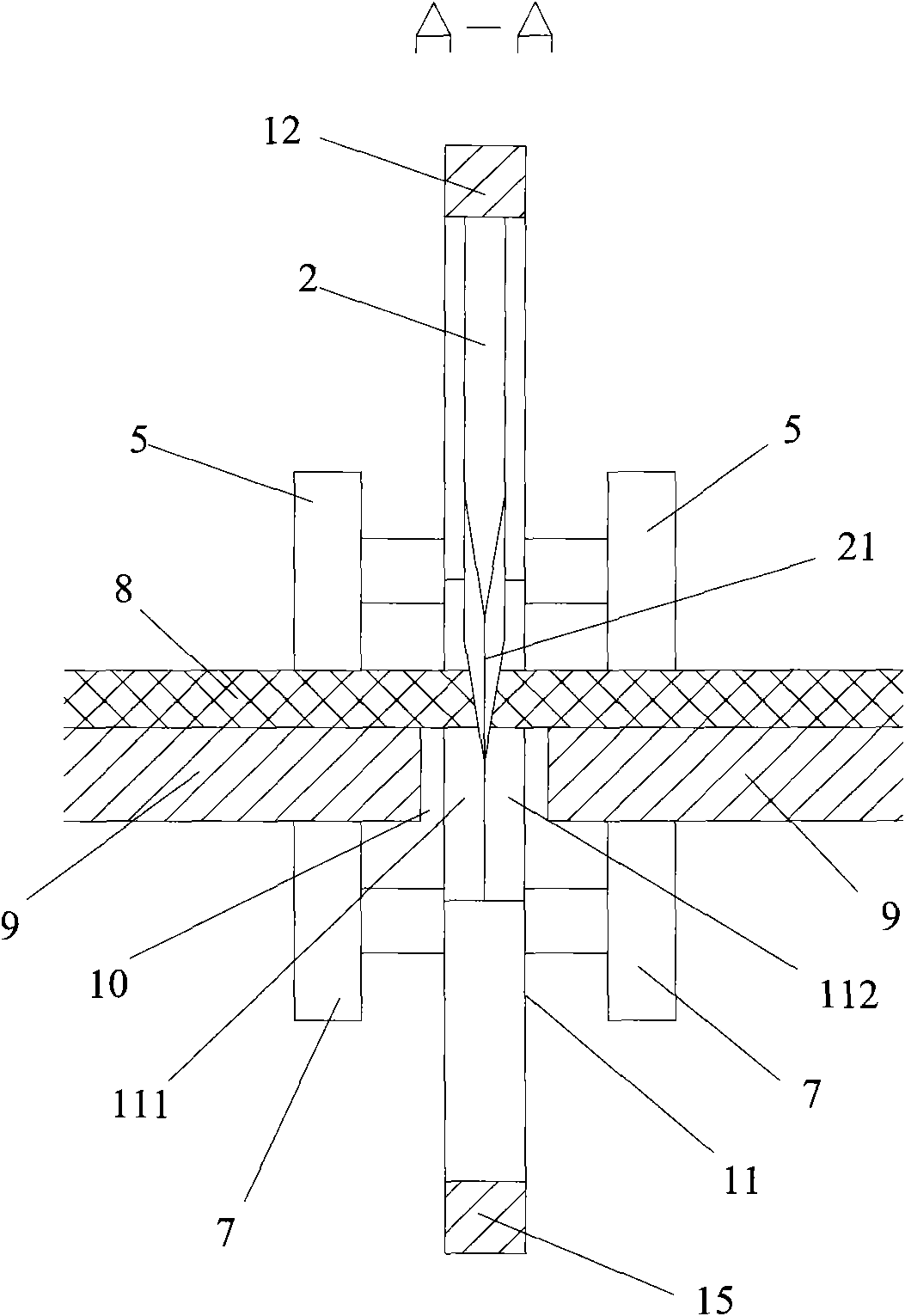
[0026] Embodiment two, figure 1 It is the front view of the medium cutting mechanism in the second embodiment of the present invention, figure 2 It is the medium cutting mechanism in the second embodiment of the present invention figure 1 In the sectional view of A-A, the media cutting mechanism includes: a knife holder 1 , a blade set formed by blades 2 and 3 , an upper pinch roller set 4 , an upper pinch roller set 5 , a lower pinch roller set 6 , and a lower pinch roller set 7 . The tool rest 1 is an I-shaped structure, including a column 11, an upper beam 12 connected with the upper end of the column, and upper side limbs 13 and 14 connected with the upper beam 12, a lower beam 15 connected with the lower end of the column, and a lower beam 15 connected with the lower beam 15. The lower limbs 16 and 17 are connected. The blades 2 and 3 are installed on the upper beam 12 of the tool holder 1 and are distributed on both sides of the column 11 . The upper pressing wheel g...


PUM


Abstract

The invention discloses equipment containing a medium cutting mechanism. Medium is placed on a medium support plate, and a support plate gap is arranged on the medium support plate. The medium cuttingmechanism comprises a tool holder, a first blade or a first blade set, a first upper pressure wheel set and a second upper pressure wheel set, wherein the tool holder comprises an upper beam and twoupper side limbs which are connected with the upper beam, the first blade or the first blade set is installed on the upper beam of the tool holder, the first upper pressure wheel set and the second upper pressure wheel set are respectively installed at the end parts of the upper side limbs of the tool holder to press the medium by bestriding both sides of the support plate gap, and the width of the support plate gap is greater than the thickness of the first blade or blades of the first blade set. Because the medium cutting mechanism can only move along the direction of the support plate gap in the technical scheme, a cutting seam is straight, and only one traction force is needed along the direction of the support plate gap, therefore, the invention has simple operation and high efficiency, and can finish the operation by only needing one person or by automatic control.

Description

technical field [0001] The invention relates to the technical field of media cutting, in particular to a device including a media cutting mechanism. Background technique [0002] At present, for most of the roll-to-roll and roll-to-sheet inkjet printers on the market, when cutting the medium, it is generally manually cut with scissors or cut with a knife, which is troublesome to operate and the cutting seam is not straight. Especially when cutting roll-to-sheet media, since the operator cannot step on the media or drill under the media, several people are needed to help to pull the cut media apart to complete. [0003] During the research and practice of the prior art, the inventors of the present invention found that the manual cutting slits are not straight, the cutting quality is not high, which affects the appearance, requires the cooperation of many people, and the cutting is cumbersome and inefficient. Contents of the invention [0004] An embodiment of the present ...

Claims


Application Information

Patent Timeline
IPC IPC(8): B26D1/03B26D7/26
Inventor 江洪金世华李力
Owner SHENZHEN RUNTIANZHI DIGITAL EQUIP
Why Eureka
Try Eureka