Warping device

A technology of guiding device and supporting device, applied in warping machine, textile and papermaking, rewinding machine, etc., can solve the problem of occupying production time and so on

Active Publication Date: 2010-02-17
KARL MAYER STOLL R&D GMBH
View PDF0 Cites 7 Cited by
  • Summary
  • Abstract
  • Description
  • Claims
  • Application Information

AI Technical Summary

Problems solved by technology

[0004] Especially in the case of short warp yarns, rewinding takes up a relatively large part of the production time

Method used


Image

  • Warping device
  • Warping device
  • Warping device

Examples


Embodiment Construction

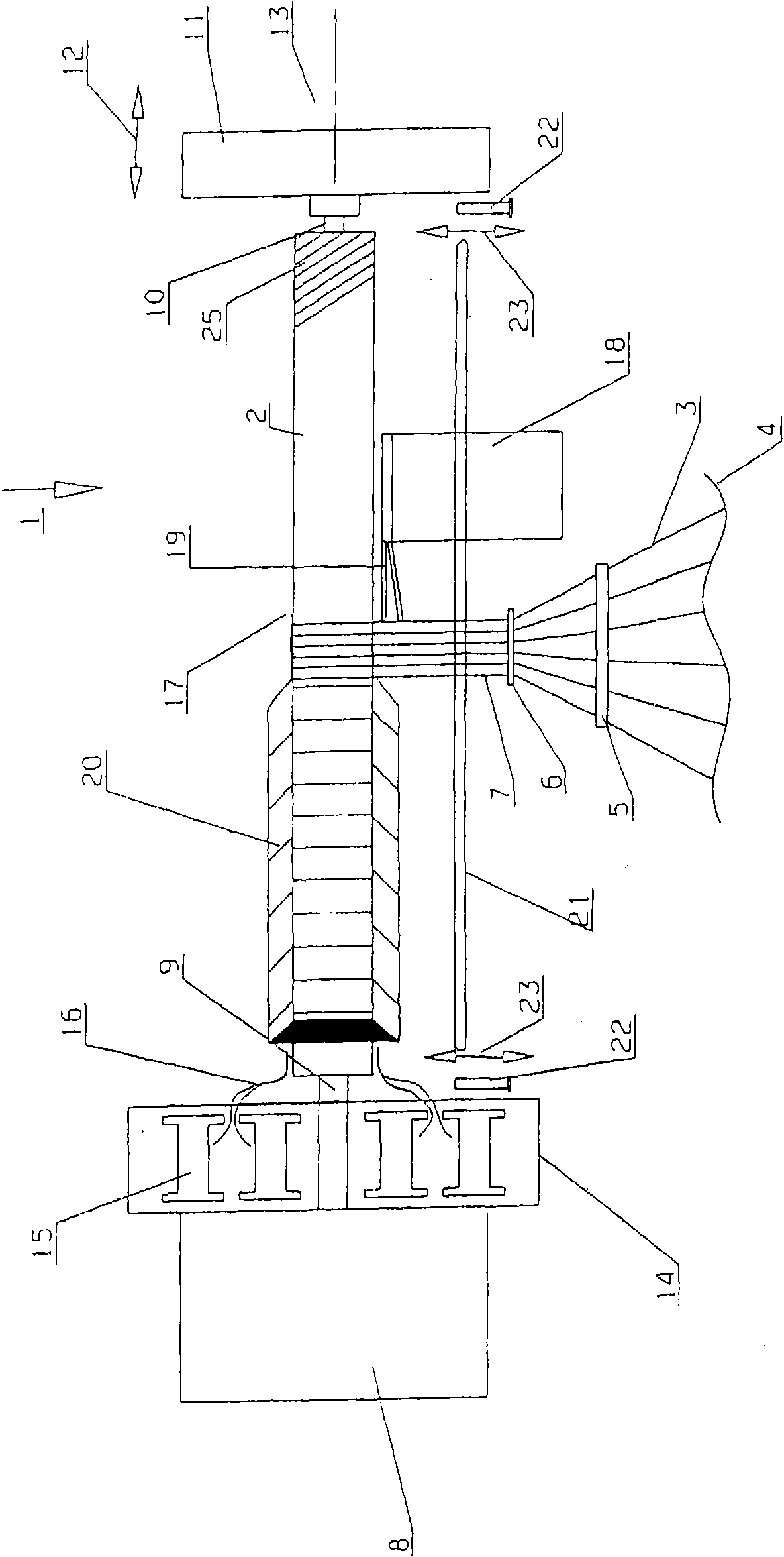
[0021] figure 1 A warping device 1 is shown in extremely simplified form, comprising a creel designed as a warp beam 2 , on which creel a yarn 3 unwound from a creel 4 is wound. The yarn 3 is passed through a cross-twisting device 5 and then through a warping reed 6 in which the yarn is finally combined into a yarn tape 7 .

[0022] The warp beam 2 is connected to a rotary drive 8 . For this purpose, the warp beam 2 has at one axial end a warp beam carrier 9 which, by means of a follower, not shown in detail, engages in a rotationally fixed engagement with the rotary drive 8 .

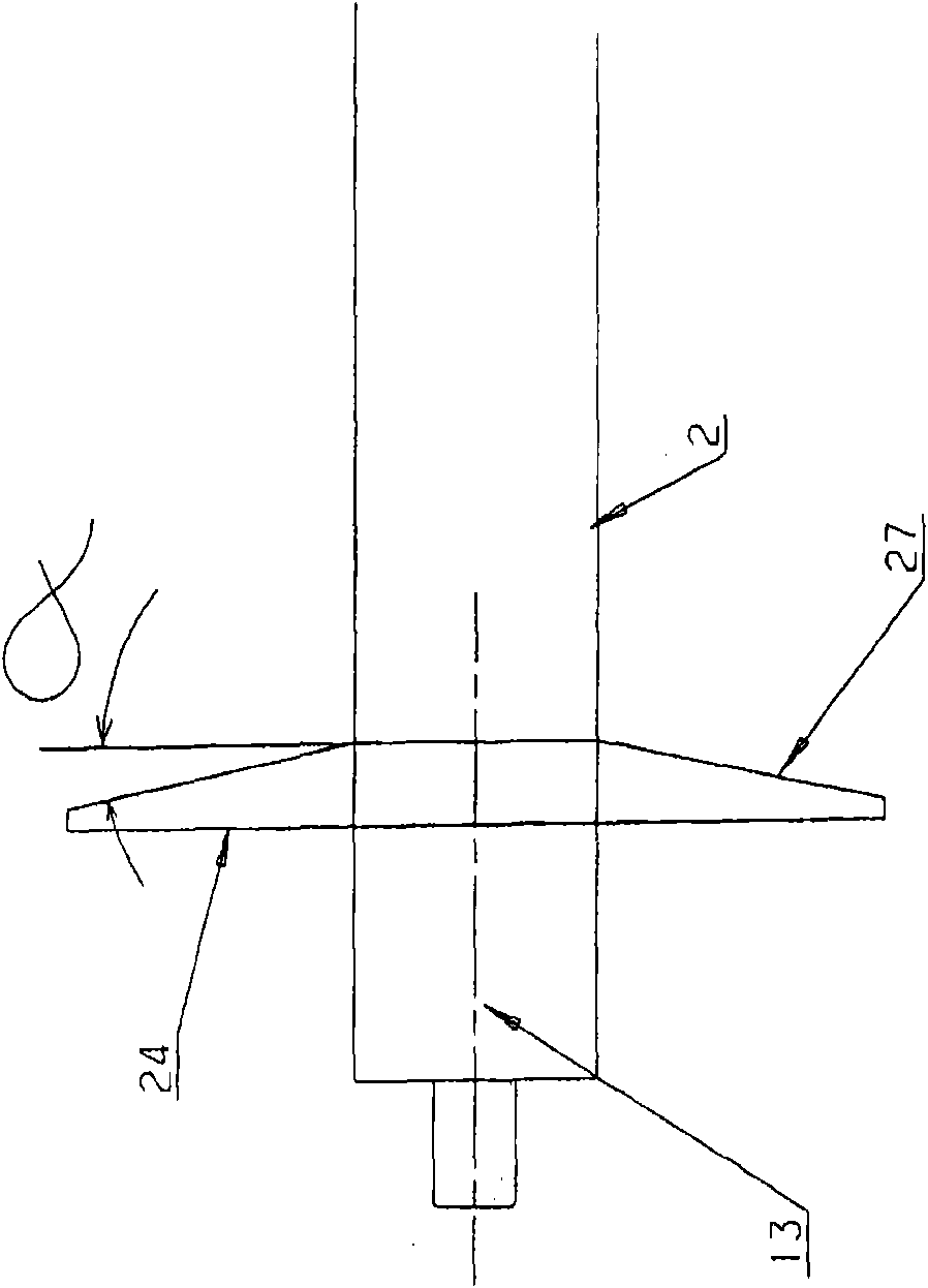
[0023] On the opposite end, the warp beam 2 has a further warp beam support 10 , which is supported in an opposing support 11 . This counter-support 11 is movable in the direction of the double arrow 12 , that is to say parallel to the axis 13 of the warp beam 2 . Thus, the warp beam 2 can firstly be brought into engagement at one end with its warp beam support 9 with the rotary drive 8, and then th...


PUM


Abstract

The invention relates to a warping device (1), which has a winding carrier, a rotation drive (8) that rotationally drives the winding carrier, a bearing unit (11) for the winding carrier and a threadband guiding device moved along the winding carrier. For the purpose that the production time can be short in the process of producing warp threads by the warping device, the warping device is designed in the following way: the winding carrier is designed into a yarn beam (2) which can be detachably connected with the rotation drive (8) and bearing unit (11) and has at least one yarn beam plate (24).

Description

technical field [0001] The present invention relates to a warping device ( ), which includes a bobbin frame ( ), a rotary drive device for rotatably driving the bobbin frame, a bobbin frame supporting device, and a yarn sheet guiding device capable of moving along the bobbin frame. Background technique [0002] Such a warping device is usually designed as a cone warping device with a coil carrier, which is designed as a warping cylinder. With this warping device, so-called segment warping can be carried out automatically. During section warping, yarn pieces in the form of so-called "belts" or "tapes" are unwound from creels and wound onto warping cylinders in the desired length. Simultaneously with each revolution of the warping cylinder, the sheet guiding device is moved towards one end of the warping cylinder by a predetermined amount, thereby obtaining a conical configuration of the loops. Thus, the yarn is prevented from falling down at the free end face of the loo...

Claims


Application Information

Patent Timeline
Patent Type & Authority Applications(China)
IPC IPC(8): D02H3/00D02H13/28
CPCD02H3/02D02H3/00D02H7/00
Inventor M·富尔
Owner KARL MAYER STOLL R&D GMBH
Why Eureka
Try Eureka